


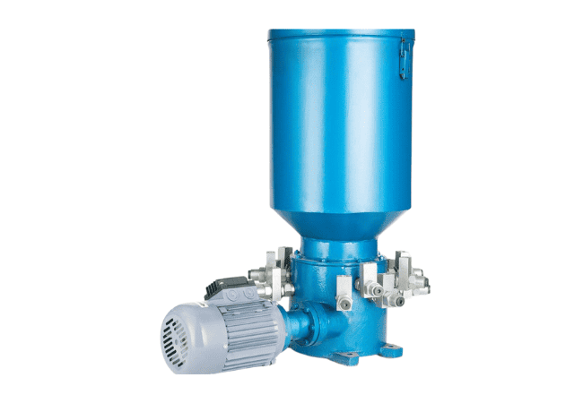


DDRB Multipoint Grease Pump
The DDRB multipoint grease pump is an electric central station for medium and large grease systems—metallurgy, mining, forging, rubber, and construction hosts that need reliable pressure over long main lines. Rated to 32 MPa, one drive unit powers 1–14 pump elements, each feeding a branch or main header for dual-line, progressive, or air-assisted circuits.
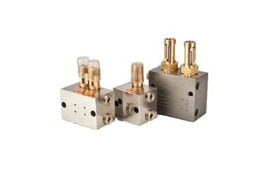
Typical configuration: discharge per element 1.8 / 3.5 / 5.8 / 10.5 ml per stroke; cycle rate about 22 strokes/min; reservoir 10 kg or 30 kg; motor 0.37 kW; weight about 55 kg (outlet count and tank size dependent). Pair with VSG dual-line distributors, ZVB blocks, DR45 changeover valves, and progressive manifolds on Related Products.
DDRB sits between compact FS progressive pumps and full BS-B dual-line skids—enough pressure and multipoint flow for spread-out plants without a 60–100 kg central station. For modular high-point builds see DDRB-N. Hub: grease pump · dual-line lubrication system · progressive systems.
- Main Characteristics Of DDRB Multipoint Grease Pump
DDRB multipoint grease pump — main characteristics
| Parameter | Value |
|---|---|
| Outlets (pump elements) | 1–14 |
| Rated pressure | 32 MPa |
| Discharge / stroke (element option) | 1.8 / 3.5 / 5.8 / 10.5 ml |
| Cycle rate | ~22 strokes/min |
| Reservoir | 10 kg / 30 kg |
| Motor power | 0.37 kW |
| Approx. weight | ~55 kg (configuration dependent) |
| Lubricant | NLGI #0–#2 grease (confirm grade with application) |
| System pairing | Dual-line · progressive · air-assisted supply |
Discharge Options & Hourly Output (per element)
At 22 strokes/min, approximate delivery per outlet:
| ml/stroke | ml/min | L/hour (single element) |
|---|---|---|
| 1.8 | 39.6 | ~2.4 L/h |
| 3.5 | 77.0 | ~4.6 L/h |
| 5.8 | 127.6 | ~7.7 L/h |
| 10.5 | 231.0 | ~13.9 L/h |
Multiply by active outlet count for total pump output; size reservoir refill interval against daily consumption (typically refill before tank drops below 25%).
DDRB vs Other Central Grease Pumps
| Pump | Pressure | Reservoir | Best for |
|---|---|---|---|
| DDRB (this page) | 32 MPa | 10 / 30 kg | 1–14 multipoint lines; dual-line or progressive headers |
| FS grease pump | ~20 MPa class | Smaller integrated tank | Machine-mounted progressive circuits |
| BS-B dual-line | 40 MPa | 30–100 kg | Full plant dual-line with reversing valve |
| Barrel pump | Transfer duty | 180 kg drum | Refill station—not primary cycle pump |
Choose DDRB when point count and line length exceed compact FS units but a full BS-B skid is not required. Confirm NLGI grade and ambient temperature with application engineering before order.
How To Fix And Remove The Pump Element
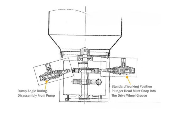
When removing the pump element, begin by detaching the grease supply pipes. Then, proceed to loosen the connecting nut 7. Gently tilt the pump element piston upward by approximately 30 degrees. Once the grease piston is separated from the drive wheel, the pump element can be safely lifted.
During removing the pump element, it’s essential not to insert the working plug at one end to prevent any accidental damage to the piston due to slippage.
For the installation of the pump element, follow these steps:
- Extend the working piston one out by around 30mm.
- Place it horizontally within the mounting screw hole.
- Lift the working piston 1 to an angle of about 30 degrees.
- Ensure that the end of the working piston is correctly positioned into the groove of the drive wheel.
- Securely tighten the connection nut 7.
Adhering to these guidelines ensures a smooth and damage-free process for both pump element removal and installation.
Dimension Of The DDB Multipoint Grease Pump


Pump Element For Ddrb Grease Pump
- Pressure Piston
- Adjustable Piston
- Adjustable bolt
- Check Valve
Related Product
DDRB Multipoint Pump in Centralized Grease Systems
What DDRB Does
DDRB is a multipoint reciprocating grease pump: one motor and drive wheel actuate several independent pump elements mounted on a common manifold. On each forward stroke, each element displaces a fixed volume of grease into its outlet port; check valves hold line pressure on the return stroke while the chamber refills from the reservoir. Because each element can feed a separate main line or zone, DDRB replaces multiple small pumps on one machine frame or in one lube room.
At 32 MPa, DDRB generates enough pressure to operate dual-line metering blocks over long pipe runs, or to charge progressive divider stacks and SSV manifolds on large hosts. Typical plant working pressure stays in the 20–35 MPa band depending on NLGI grade, ambient temperature, and line length.
Stroke Cycle (One Pump Element)
- Fill — grease enters the element chamber from the tank through suction path; follower plate (if fitted) maintains head on thick NLGI #2.
- Forward stroke — drive wheel pushes the working piston; outlet check valve opens; fixed ml volume enters the connected main line.
- Return stroke — piston retracts; outlet check closes; inlet path refills chamber for next cycle.
- Controller — timer or machine interlock sets run duration; pressure relief protects pump if a line blocks.
With 22 strokes/min and 10.5 ml/stroke on one element, a single outlet delivers roughly 13.9 L/hour—useful for sizing whether a 10 kg or 30 kg tank matches your refill interval.
Typical System Layouts
- Dual-line plant — DDRB → main lines A/B → DR45 or SA-V reverse valve → VSG / ZVB / VSL blocks → bearings. One DDRB element may feed each header zone on very large spreads.
- Progressive machine circuit — DDRB → single header → progressive manifolds (DJF1000 / DJF2000 / DJF3000 or SSV) → way covers, pins, and bushings. Monitor cycle pin or limit switch on last block.
- Multi-zone progressive — several DDRB elements each feed a separate progressive chain (e.g. turret, boom, and base on a crane).
- Long-distance supply — 30 kg tank and higher ml/stroke options reduce refill frequency when the pump sits remote from the host.
Industry Applications
- Metallurgy & steel — rolling mill stands, continuous casters, descaling equipment
- Mining — crushers, conveyors, apron feeders, shovel swing bearings
- Forging & presses — slide guides, ejector pins, high-load bushings
- Rubber & construction — mixers, extruders, mobile crane booms
For installation support on new builds, see lubrication service and heavy equipment lubrication system hub pages.
DDRB vs BS-B vs FS — When to Choose DDRB
| Criteria | DDRB | BS-B dual-line | FS progressive |
|---|---|---|---|
| Architecture | Multipoint reciprocating elements | Single high-flow pump + reversing valve | Single progressive feed pump |
| Pressure class | 32 MPa | 40 MPa | ~20 MPa typical |
| Outlets from pump | 1–14 independent elements | 2 main headers (A/B) | 1 header |
| Reservoir | 10 / 30 kg | 30–100 kg | Compact integrated |
| Ideal plant | Medium spread, mixed zones | Large dual-line steel/cement plant | Single machine OEM progressive |
Choose DDRB when you need several feed lines from one skid at 32 MPa. Step up to BS-B when the entire plant runs on dual-line headers with 40 MPa and 60 kg+ daily consumption. Use FS for smaller machine-mounted progressive only.
Five-Step Selection
- Count points and dose — list each bearing with ml/cycle from OEM chart or bearing lubrication calculator; sum peak demand per cycle.
- Choose ml/stroke per element — pick 1.8–10.5 ml so one stroke supplies the connected header without excessive over-lubrication; match pump run time to production schedule.
- Confirm pressure class — 32 MPa rating must exceed downstream block cracking pressure plus line losses (long Φ8 mm runs and NLGI #2 in cold plants need margin).
- Reservoir — 10 kg for moderate single-shift use; 30 kg for multi-shift or weekly refill targets. Estimate: (total ml/min × 60 × run hours) ÷ 1000 vs usable tank volume.
- Pair valves and blocks — dual-line needs changeover, end-of-line pressure switch, and block family rated for your pressure; progressive needs cycle indicator or electric switch on last block for fault stop.
Commissioning & Grease Fill
- Mount pump level, rigid frame, and vibration isolation per OEM drawing (Section 2 shows dimensions).
- Fill with specified NLGI #0–#2 grease only—no oil or mixed grades.
- Run several cycles with outlets capped to prime each element; verify even stroke sound.
- Connect main lines; open branches progressively; purge air at highest points and block bleed screws.
- For dual-line, confirm DR45/SA-V switches at set pressure; for progressive, confirm indicator pin completes one full travel per pump run.
- Set controller interval; log first-week consumption to validate tank size.
Pump Element Service
Section 2 on this page covers removal and installation of DDRB pump elements—critical steps include tilting the piston ~30° when disengaging from the drive wheel and never inserting the working plug during removal (prevents piston damage). After element swap, purge air on the affected branch before returning to automatic cycle. Adjustable pistons and check valves are shown in Section 2 diagrams—replace seals when stroke volume drops or suction cavitation is heard.
Maintenance Schedule
- Each shift: check reservoir level and abnormal noise from drive wheel
- Weekly: inspect outlet fittings for leaks; verify controller cycle count
- Monthly: clean fill port strainer; sample grease for contamination in dusty plants
- Quarterly: inspect pump element seals; verify relief valve setting
- Annual: replace worn elements; review line hoses and grease filter if fitted on fill path
Troubleshooting
| Symptom | Likely cause | Action |
|---|---|---|
| No pressure on one outlet only | Failed element check valve or worn piston | Replace or rebuild that pump element (see Section 2) |
| Low pressure on all outlets | Empty tank, air lock, wrong NLGI grade | Refill; bleed air; confirm grease pumpability at ambient temp |
| Pump runs but lines do not advance | Blocked bearing or stalled progressive chain | Find blocked point; progressive systems stall until cleared |
| Dual-line does not reverse | DR45/SA-V stuck or set pressure too high | Service reversing valve; adjust relief per manual |
| Short element life | Contaminated grease or dry running | Filter fill grease; add low-level alarm |
| Motor overload trips | Line blockage or relief too tight | Clear blockage; verify relief setting against 32 MPa rating |
Ordering Checklist
Provide: outlet count (1–14), ml/stroke per element, tank size (10 / 30 kg), voltage, intended system type (dual-line / progressive), NLGI grade, ambient temperature range, and paired block models (VSG, ZVB, DJF, etc.). IsoHiTech application engineering can confirm BOM against Related Products on this page.
Related Products
- BS-B dual-system grease pump — larger integrated dual-line skids
- FS grease pump — compact progressive-friendly pumps
- DDRB-N multi-point module — expandable multipoint builds
- Installation and commissioning service
Before you buy: read our central lubrication system guide.
A multipoint grease pump drives several pump elements from one motor, delivering metered grease to multiple lines or high-flow branches. DDRB supports 1–14 outlets at 32 MPa for mining, steel, forging, and heavy construction—see the grease pump hub for smaller reservoir models.
No. DDRB is for grease central systems (NLGI #0–#2). For oil circulation use lubrication oil pumps or lube oil pump products rated for ISO VG fluids.
Each pump element feeds one main line or zone. With 1–14 elements, DDRB can supply up to fourteen independent headers; total bearing count depends on downstream dual-line blocks or progressive stacks on those lines—not outlet count alone.
Match ml/stroke to the header demand per cycle. Lower values (1.8–3.5 ml) suit small progressive chains; 5.8–10.5 ml feed larger dual-line zones or long main lines. At 22 strokes/min, multiply ml/stroke × 22 × 60 for hourly output per element.
Use DDRB for 32 MPa multipoint feeds with 10–30 kg tanks. Choose BS-B when the whole plant runs on 40 MPa dual-line headers with 30–100 kg reservoirs and a single reversing-valve cycle.
Yes. DDRB commonly feeds progressive manifolds (DJF, SSV, or grease manifold blocks) on one supply line. Install a cycle monitor on the last block so the machine stops if the chain stalls.
Follow Section 2 on this page: disconnect grease pipes, loosen the connecting nut, tilt the piston ~30° to clear the drive wheel, and lift the element. Do not insert the working plug during removal. After installation, tighten the nut and purge air on that branch.
Typically NLGI #0, #1, and #2 lithium or calcium greases within the pump’s temperature range. Confirm pumpability at your plant’s minimum ambient temperature—thick NLGI #2 in cold starts may need shorter line runs or a lower NLGI grade.