


The figures, examples, and brand names in this article are illustrative. IsoHiTech is an independent supplier of lubrication components and is not affiliated with the OEMs or third-party brands mentioned.
Grease pump failures in industrial environments usually follow a small set of recurring patterns. A methodical diagnostic approach—checking power or air supply, lubricant condition, pump element operation, and distribution network integrity—is generally more effective than replacing parts at random. This guide summarizes common failure modes and troubleshooting steps for pump elements, pneumatic and electric grease pumps, and centralized lubrication systems. For background on pump designs, see the guide to grease pumps.
Contents
- How a Pump Element Works
- Systematic Diagnostic Framework
- Lincoln Grease Pump Troubleshooting
- Pneumatic Grease Pump Analysis
- Central Lubrication System Diagnostics
- Oilfield and Severe-Service Considerations
- Preventive Maintenance Protocols
- When to Repair or Replace
- People Also Ask
- Conclusion
How a Pump Element Works

A pump element is the pressure-generating component in many grease pumps. It typically contains an inlet, an outlet, a piston or plunger, and one or more check valves. During the intake stroke, the piston retracts and draws grease through the inlet valve into the pumping chamber. During the discharge stroke, the inlet valve closes, the outlet valve opens, and grease is forced toward the distribution line. The cycle repeats to maintain flow to the lubrication point.
Pump element performance depends on piston and valve geometry, grease viscosity, inlet supply, and the back-pressure created by the distribution network. If a check valve cannot seat because of contamination or wear, the element cannot build pressure and the lubrication system may starve critical points.
Systematic Diagnostic Framework
Effective grease pump troubleshooting begins with verifying basic operating conditions before disassembling components. Most failures can be traced to air or power supply issues, contaminated or incorrect lubricant, control or sensor faults, and mechanical wear.
Primary Assessment Protocol
Step 1: Verify utility supply.
- For pneumatic pumps, confirm inlet pressure and flow capacity at the pump under load, not only at the compressor. Many industrial pneumatic grease pumps are rated near 80–100 PSI, but the manufacturer’s specification should govern.
- For electric pumps, verify supply voltage and motor rotation direction.
- Confirm that the reservoir contains the correct grease grade and that the grease is not hardened, separated, or contaminated.
Step 2: Test basic response.
- Attempt manual or local activation and observe whether the motor or air motor runs.
- Record pressure gauge readings during operation, if available.
- Document any error codes or abnormal cycling behavior.
Step 3: Verify flow.
- Measure or observe output at the primary distribution points.
- Check for air bubbles, erratic flow, or no flow at the outlets.
- Compare behavior across several cycles to identify intermittent faults.
Common Failure Patterns
| Failure Mode | Primary Indicators | Diagnostic Priority |
|---|---|---|
| Air supply issues | Erratic cycling, slow operation, low pressure | Check compressor capacity, line sizing, and inlet pressure at the pump |
| Contamination | Inconsistent flow, sticking valves, component wear | Inspect grease condition, filters, and reservoir seals |
| Control failures | Timing errors, missed cycles, sensor faults | Test timers, pressure switches, and controller inputs |
| Mechanical wear | Internal leakage, seal failure, loss of prime | Disassemble and measure pump element clearances |
Lincoln Grease Pump Troubleshooting
The Lincoln P203 and similar progressive lubrication pumps are widely used in industrial installations. The diagnosis procedures below apply to comparable progressive systems; consult the OEM service manual for model-specific pressures, torques, and parts.
Motor Runs But No Grease Output
If the pump motor runs but no grease is delivered, check the following:
- Electrical connections and rotation: On three-phase or reversible motors, incorrect rotation direction will prevent priming. Many pumps mark polarity or phase wiring to simplify correct connection.
- Air in the system: Air entrainment is common after grease refills, especially when grease is added from the top of an open reservoir. The recommended practice is to add grease through the bottom fill port or grease fitting when one is provided. Cycling the pump after adding a small amount of lower-viscosity grease or compatible thinning oil can help purge air.
- Reservoir condition: Verify that the grease is pumpable at the current ambient temperature and that the reservoir is not empty or blocked.
No Pressure: Grease Cannot Reach Lubrication Points
- Pipeline leakage: External leaks at fittings, couplings, or hoses prevent pressure buildup. Inspect the entire distribution path.
- Pump element failure: Contaminated grease can prevent check valves from seating fully, eliminating pressure generation. In most cases the pump element body remains intact; the fault is in the valves, seals, or contamination. Flush the system before installing a replacement element.
- Relief valve or pressure regulation: A stuck-open relief valve or incorrect pressure setting can bypass flow back to the reservoir.
Progressive Distributor Failure Analysis
A progressive distributor that fails to advance sequentially is often obstructed by contaminated grease. The typical service procedure is:
- Remove the distributor block and disassemble the piston assemblies.
- Clean the components with a solvent compatible with the seals. Petroleum-based solvents can damage many elastomer seals.
- Replace seals that show hardening, cuts, or contamination damage.
- Reassemble using the manufacturer-specified torque values.
Pressure Generation Issues
If a Lincoln P203-type system cannot reach its normal operating pressure range, isolate the pump element from the distribution network:
- Disconnect the outlet line and cycle the pump manually. Consistent grease flow indicates that the pump element is likely healthy and the restriction is downstream.
- Intermittent or weak flow from the pump element suggests inlet check valve contamination or outlet valve seat wear.
- Typical operating pressures for these systems commonly fall between 50 and 200 PSI; confirm the exact range in the manufacturer documentation.
Proper Grease Addition Procedure
Minimizing air entrainment during refills reduces priming problems and false “no-output” faults. Where possible, refill through the designated bottom port, keep grease containers sealed, and allow the pump to cycle several times before returning the system to automatic mode. For visual reference, see the Lincoln/SKF demonstration video below.
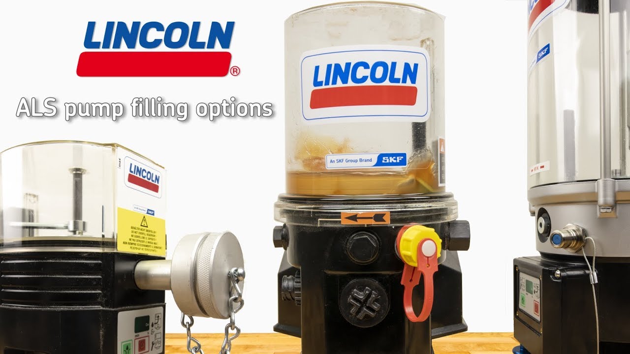
Demonstration of a bottom-fill grease addition technique to reduce air entrainment. Video courtesy of the equipment manufacturer’s technical channel.
Battery-Powered and Automatic Greaser Issues
Battery-operated automatic greasers can fail when an incorrect battery type is used or when voltage regulation differs from the manufacturer’s specification. Programming errors and grease viscosity mismatches are also common causes of apparent failures. For example, NLGI 2 grease may become difficult to pump at very low temperatures. For an overview of these units, see the automatic grease pump page.
Pneumatic Grease Pump Analysis
Pneumatic grease pump reliability depends heavily on air quality and stable inlet pressure. Poor air supply can mask itself as a pump failure.
Air Supply Requirements
- Pressure: Measure pressure at the pump inlet while the pump is cycling. Static readings at the compressor can be significantly higher than dynamic pressure under load. If the manufacturer specifies an inlet pressure, use that value as the minimum.
- Air quality: Contaminated or wet air accelerates seal wear and causes erratic cycling. Where possible, install filtration and drying upstream of the pump. Many industrial air-quality standards, such as ISO 8573-1, provide classification guidance for particle, moisture, and oil content.
Pneumatic Component Diagnosis
- Control valve: Slow cycling or mid-stroke stalling can indicate a sticking control valve. Remove the air supply, test manual operation, and clean the valve assembly with compressed air and a light machine oil if the manufacturer permits.
- Air motor: If the pump cycles but generates little or no pressure, the air motor may be worn or its seals damaged. Compare rebuild cost with replacement cost and consider parts availability before deciding on repair.
Central Lubrication System Diagnostics
Centralized lubrication systems fail when any part of the pump-to-point chain is interrupted. Because outlets are interdependent, a single fault can appear as a system-wide problem.
Progressive Distribution System Analysis
- Sequential operation: Progressive distributors must advance in sequence. Simultaneous outlet activation generally indicates excessive inlet pressure or internal contamination.
- Pressure verification: Measure pressure at the primary distributor inlet and at each downstream level. Pressure drops between stages can reveal blockages or leaks.
- Contamination sensitivity: Progressive distributors have tight clearances and are more sensitive to contaminated grease than simple pump-to-point systems.
Dual-Line System Operations
Dual-line systems alternate pressure between two main distribution lines. Proper operation depends on accurate changeover timing and complete pressure transfer:
- Verify timer or controller settings against the system design.
- Test pressure switch switching points and response time.
- Confirm that the changeover valve fully pressurizes each line.
Oilfield and Severe-Service Considerations
Oilfield and remote installations add environmental severity to ordinary grease pump failures. Diagnosis should include temperature, contamination, and vibration factors.
Environmental Challenge Mitigation
- Temperature: Select a grease with a viscosity index suitable for the operating range, and verify that seals and electrical components are rated for the ambient conditions. Heating or cooling accessories may be required in extreme environments.
- Contamination control: Dusty conditions may require upstream pre-filtration, sealed IP-rated reservoirs, and effective breather systems.
- Vibration: Drilling and pumping equipment can subject lubrication systems to vibration beyond standard ratings. Vibration-resistant fasteners, flexible connections, and shock-absorbing mounts may be necessary.
Remote Location Considerations
Remote sites benefit from on-site spare parts and trained personnel because service response times are longer. A typical spare-parts inventory might include pump element rebuild kits, control valve assemblies, rated hose, pressure gauges, and basic diagnostic tools.
Preventive Maintenance Protocols
Structured maintenance reduces unplanned grease pump failures. The following schedule is a general guideline; severe-duty applications require shorter intervals.
| Interval | Task | Typical Duration |
|---|---|---|
| Daily | Visual inspection, reservoir level check | A few minutes |
| Weekly | Pressure and cycle timing verification | About 15 minutes |
| Monthly | Filter inspection, connection tightening | About 30 minutes |
| Quarterly | Grease condition review, full system evaluation | 1–2 hours |
| Annually | Pump element service or replacement, comprehensive rebuild | Half to full day |
Performance Monitoring
- Track lubricant consumption against a baseline.
- Record system pressure and cycle timing over time.
- Log component replacements and failure frequency to identify trends.
For additional background on pump types and maintenance, see the lubrication pump guide.
When to Repair or Replace
Repair-versus-replace decisions should balance cost, parts availability, failure history, and system age. General considerations include:
- Repair costs that approach or exceed the cost of a new pump unit.
- Recurring failures that indicate worn components or outdated controls.
- Systems older than five years where replacement parts are scarce or technology has changed significantly.
- Safety-critical applications where reliable operation outweighs incremental repair cost.
People Also Ask
Why does a grease pump stop working?
The most common causes are loss of prime from air entrainment, insufficient air or electrical supply, contaminated or hardened grease, and worn pump elements or check valves. A systematic check of supply, lubricant, and mechanical components identifies most faults quickly. See Systematic Diagnostic Framework.
How is a grease pump troubleshot?
Start by verifying power or air supply, reservoir level, and grease grade. Then test pump response and output flow, inspect distribution lines for leaks, and isolate the pump element to check pressure generation. Document symptoms before disassembling components. See Lincoln Grease Pump Troubleshooting.
What causes a grease pump to lose pressure?
Pressure loss usually results from pipeline leaks, check valves that cannot seat because of contamination or wear, a stuck-open relief valve, or insufficient inlet pressure on pneumatic units. See Pneumatic Grease Pump Analysis.
How is a grease pump primed?
Priming is easiest when grease is added through the designated bottom fill port, air pockets are vented, and the pump is cycled slowly. Adding a small amount of compatible lower-viscosity lubricant and running several cycles can help purge trapped air. See Lincoln Grease Pump Troubleshooting.
When should a grease pump be repaired or replaced?
Replace or overhaul the pump when repair costs approach replacement cost, failures recur, parts are no longer available, or the system no longer meets reliability requirements. See When to Repair or Replace.
Conclusion: grease pump not working
Effective grease pump troubleshooting relies on a structured diagnostic sequence: verify supply and lubricant condition, isolate the pump element, inspect the distribution network, and address root causes rather than symptoms. Regular maintenance and proper refill procedures prevent many common failures. For systems that remain unresolved, manufacturer technical support or a qualified service provider should be consulted.
Related technical resources: guide to grease pumps, automatic lubrication systems, and the grease pump hub.

