



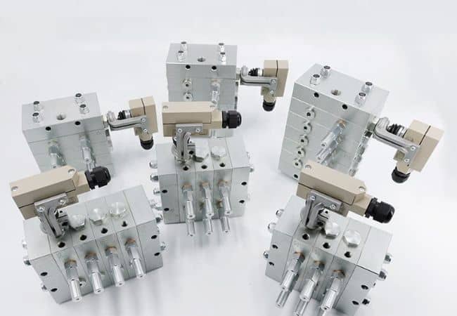


DJF3000 Progressive Distributor Block
The DJF3000 progressive distributor block is a carbon steel metering stack for demanding single-line plants—machine tools, harbor cranes, steel processing lines, and large industrial frames where each bearing needs a higher dose per cycle than compact 1000/2500 blocks can deliver. Viton seals support wider temperature swing than light aluminum manifolds. Up to 10 working slices feed 3–20 outlets on one progressive chain.
Max working pressure: 25 MPa. Discharge: 0.4–4.8 ml/cycle per outlet (size code 25–150, T/S dependent). Lubricants: oil ≥ ISO VG 68; grease NLGI #000–#2. Temperature: -20°C to +60°C. Twin outlet slices (T) discharge both ends; single (S) one side—do not plug unused ports or the progressive chain will stall and overpressurize.
Series: DJF1000 (16 MPa, aluminum) · DJF2000 (25 MPa, carbon steel) · DJF2500 (25 MPa, finest 0.08 ml/cyc twin) · progressive hub · progressive systems.
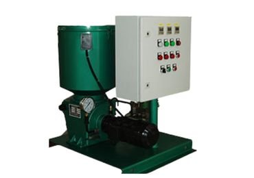
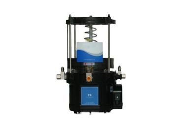
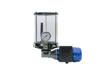
Pair with BSB pump, FS grease pump, and electric stations on Related Products.
- Features
- Product Video
DJF3000 Features
- Carbon steel body — rigid manifold for high-pressure progressive circuits on machine tools and heavy industry
- Viton O-rings — elevated temperature tolerance vs standard NBR in compact blocks
- Highest ml/cyc in DJF family — up to 4.8 ml/cycle on single size-150 outlets for large bearings and slides
- Modular slices — add, replace, or resize sections without disconnecting every tube run
- Cycle indicator / type 8 switch — pin stroke or electromechanical pulse confirms full stack progression
- Cross-port kit 32266-4 — line crossover for complex machine-tool layouts
DJF3000 Technical Summary
| Parameter | Value |
|---|---|
| Max working pressure | 25 MPa |
| Delivery per outlet / cycle | 0.4–4.8 ml/cyc |
| Manifold material | Carbon steel |
| Seals | Viton |
| Working slices | 3–10 |
| Total outlets | 3–20 (layout dependent) |
| Inlet tube | Φ10 mm (1.8–5.5 m typical) |
| Outlet tube | Φ8 mm (1.5–4.5 m typical) |
| Fill filter (grease) | 150 μm recommended in dusty plants |
| Max frequency (with cycle pin) | 60 cyc/min |
| Max frequency (without pin) | 200 cyc/min |
Size Codes (T = twin, S = single)
| Size | Valve P/N | mL/cyc | Outlet P/N |
|---|---|---|---|
| 25 | 3000-25T / 3000-25S | 0.4 / 0.8 | 20730-25T / 20730-25S |
| 50 | 3000-50T / 3000-50S | 0.8 / 1.6 | 20730-50T / 20730-50S |
| 75 | 3000-75T / 3000-75S | 1.2 / 2.4 | 20730-75T / 20730-75S |
| 100 | 3000-100T / 3000-100S | 1.6 / 3.2 | 20730-100T / 20730-100S |
| 125 | 3000-125T / 3000-125S | 2.0 / 4.0 | 20730-125T / 20730-125S |
| 150 | 3000-150T / 3000-150S | 2.4 / 4.8 | 20730-150T / 20730-150S |
Stack Length vs Slice Count (mm)
| Slices | A | B | Slices | A | B |
|---|---|---|---|---|---|
| 3 | 128.6 | 167.9 | 7 | 242.9 | 282.2 |
| 4 | 157.1 | 196.5 | 8 | 271.4 | 310.8 |
| 5 | 185.7 | 225 | 9 | 300 | 339.9 |
| 6 | 214.3 | 253.6 | 10 | 328.6 | 367.9 |
DJF Series Comparison
| Series | Body | Pressure | ml/cyc range | Max twin dose | Best for |
|---|---|---|---|---|---|
| DJF1000 | Aluminum | 16 MPa | 0.08–0.48 | 0.08 | Compact mobile / light industry |
| DJF2000 | Carbon steel | 25 MPa | 0.16–1.12 | 0.16 | Machine tools, mid dose |
| DJF2500 | Steel, zinc-plate | 25 MPa | 0.08–1.28 | 0.08 | Fine twin doses, Viton |
| DJF3000 (this page) | Carbon steel | 25 MPa | 0.4–4.8 | 2.4 | Heavy bearings, large slides, steel |


How to Order DJF3000?
Ordering code example, main parameters, cross-port kits (32266-4 for 3000 class), and cycle-switch wiring for DJF3000 progressive stacks.
Example 2: Sketch of DJF-3000 distributor ordering
A: Indicate the type: DJF-3000;
B: indicates the number of sections (4 in this case)
C: indicates cycle indicator 8: micro switch type cycle indicator
D: contents in parenthesis indicate the sizes of sections after the first sections listed according to their sequence
E. The size of the first sections in the sequence is 35.T indicates twin outlets, and 8R shows that series 8 indicators are at the right end face of the sections.
F. The size of the second sections in the sequence is 1 on the front left side of the sections. CF placed before size 15 shows that the crossport is on the left side; if placed after size 15, the crossport will be on the right side.
G. The size of the third section in the sequence is 15. SR indicates s
H. Size of the 4th section is 10. T indicates a twin outlet.
Example decode: DJF-3000 · 4 sections · indicator 8R (micro-switch, right) · sequence 35T, 15SR, 10T with crossport notation CF left/right per drawing. Send sketch for IsoHiTech BOM confirmation.
Crossport & Switch Accessories
Crosspost
| P.N. | Description | A (mm) | B (mm) | 2-d |
| 32265-1 | 1000 cross port kit | 19 | 15 | 2-G1/8 |
| 32265-2 | 2000 cross port kit | 22 | 21 | 2-M8 |
| 32265-3 | 2500 cross port kit | 22 | 21 | 2-M8 |
| 32266-4 | 3000 cross port kit | 22 | 21 | 2-M8 |
Electromechanical switch
The electromechanical switch is a device to monitor the flow of lubricant in the system. It uses the reciprocal movement of the indicator pin on the progressive distributor’s piston to enable the electromechanical switch’s opening or closing inside the cycle indicator to send electric signals to the host control system. Once an abnormality occurs in the lubrication system, the host control system can send an alarm or stop the host’s operation to facilitate timely maintenance.
Contact capacity: 250VAC 1A or 125VAC 3A
32265-1/2/3 kits for 1000/2000/2500 class; 32266-4 for 3000 crossport. Electromechanical cycle switch for PLC monitoring—same principle as the DJF1000 page.

Related Product
How DJF3000 Progressive Metering Works
Grease or oil enters the inlet (first) slice of the DJF3000 stack and advances pistons slice by slice. Each working slice discharges a fixed volume through its T (twin) or S (single) outlets only after upstream sections complete their stroke—this is progressive (series) logic, not parallel PDI injector firing. One full movement of the cycle indicator pin (or one pulse from a type 8 electromechanical switch rated 250 VAC 1 A / 125 VAC 3 A) confirms that every connected point on that stack received its dose for that pump run.
DJF3000 slices are sized for heavier per-point delivery: even the smallest twin size 25 delivers 0.4 ml/cycle—higher than the maximum twin dose on DJF2500 (0.64 ml on size 40 twin). Size 150 single outlets reach 4.8 ml/cycle for large plain bearings, way covers, and open gears fed through progressive branches.
If one bearing line blocks, lubricant cannot pass and the chain stalls. Line pressure rises; the indicator stops; the host controller should alarm on missing cycle signal within the timeout window. That fail-safe behaviour is why machine-tool and steel-mill OEMs prefer progressive blocks over open header systems where a blocked point may go unnoticed until failure.
Typical Plant Layout
- Pump + controller — BSB, FS, or electric grease station from Related Products; size for 25 MPa at farthest outlet.
- Fill filter — 150 μm on grease fill; pair with grease filter in dusty steel or foundry environments.
- Main line — typically Φ10 mm inlet tube (1.8–5.5 m) to the DJF3000 inlet section.
- DJF3000 stack — inlet + 3–10 working slices + end section; cycle monitor on left or right face.
- Branch lines — Φ8 mm outlet tube (1.5–4.5 m) to each bearing, slide, or pin; respect max 60 cyc/min with cycle pin installed.
One manifold assembly can serve up to 20 points; larger machines may use several stacks fed from one pump header or separate zones with independent cycle monitors.
When to Choose DJF3000 (Not 1000, 2000, or 2500)
- Each point needs ≥0.4 ml/cycle on twin layout—or up to 4.8 ml/cycle on single size 150—for large bearings, way lubrication, or open gear branches.
- Plant requires 25 MPa with carbon steel body and Viton on hot machine frames or steel-mill ambient.
- Dose per point exceeds DJF2000 (0.16–1.12 ml/cyc) and DJF2500 (0.08–1.28 ml/cyc) capacity without stacking excessive slices.
- 3–20 outlets on one sequential header with modular slice replacement without full re-piping.
- Machine-tool OEM wants progressive logic with larger Φ8 mm outlet runs than compact 1000-series Φ4 mm branches.
DJF3000 vs Other Metering Architectures
| Architecture | Device | Logic | When to use |
|---|---|---|---|
| DJF3000 progressive (this page) | Sequential carbon steel slices | Series — blocked point stops chain | 25 MPa, 0.4–4.8 ml/cyc, heavy industry dose |
| DJF2500 | Steel progressive | Series | 25 MPa, finest 0.08 ml/cyc twin, Viton |
| DJF2000 | Carbon steel progressive | Series | 25 MPa, 0.16–1.12 ml/cyc mid range |
| SL1 / SL32 PDI | Injectors | Parallel on pressure rise | Per-point adjustable dose; not sequential |
| VSG / ZVB dual-line | Dual-line blocks | Alternating A/B lines | Large mining / steel with reversing valve |
| Lincoln SSV | OEM progressive | Series | Lincoln-compatible replacement builds |
Not dual-line: DJF3000 is single-line progressive only. Do not mount on A/B reversing headers without full system redesign.
Sizing a DJF3000 Stack (5 Steps)
- Point count & dose — list each bearing with ml/cycle from OEM chart or bearing calculator.
- Size code — pick 25–150 and T vs S: twin slices feed two nearby points from one section; single feeds one side only.
- Slice count — sum working slices (≤10) so total outlets ≥ point count; do not plug unused outlets—route or use correct S/T layout.
- Pressure & tube — confirm pump delivers 25 MPa at the farthest Φ8 mm outlet with your NLGI grade; heavier grease may need shorter runs or warmer fill.
- Monitor — specify mechanical pin or electromechanical switch for PLC fault stop when pin motion stops; add crossport kit 32266-4 when drawing requires line crossover.
Ordering Code Example
Example stack: DJF-3000 · 4 sections · indicator 8R (micro-switch, right face) · sequence such as 100T, 75SR, 50T with cross-port CF notation left/right per factory drawing (Section 2 sketch). Cross-port kit P/N 32266-4 (3000 class). Send machine layout for confirmed BOM.
Installation & Commissioning
- Mount with slice T/S markings visible; torque inlet/outlet fittings to spec—never block unused outlets.
- After first fill, bleed air at the highest outlet in the stack; verify one full pin stroke per pump cycle.
- Route tube through lubrication pipe and compression fittings; protect exposed runs near heat or impact zones.
- Log size codes and P/N (3000-xxT/S, outlet 20730-xxT/S) in CMMS—when a slice is replaced, match original sequence exactly.
Troubleshooting Quick Reference
| Symptom | Likely cause | Action |
|---|---|---|
| Pin never moves | Blocked outlet, air lock, pump below 25 MPa class | Clear line, bleed air, verify pump capability at farthest point |
| Pin moves partially | One slice stuck, NLGI too stiff for ambient | Isolate slices; confirm grease pumpability at temperature |
| Overpressure alarm | Plugged outlet or blocked progressive chain | Find blocked bearing—never plug ports |
| Uneven delivery | Mixed size codes after field repair | Restore original slice sequence per BOM |
| Seal weeping at slice | Worn Viton O-ring or overtightened fitting | Replace slice seals; torque to spec |
| Some points over-greased | Blocked downstream slice forcing volume elsewhere | Clear blocked line; verify full pin stroke each cycle |
Hub pages: progressive manifold · grease distributor block · metering unit · commissioning service · project cases.
Before you buy: read our guide to how distributor blocks work.
Carbon steel manifold with Viton seals for temperature and media resistance.
25 MPa—size pump, hose, and fittings to the same class.
Approximately 0.4–4.8 ml/cycle per outlet depending on size code and T/S layout.
Oil ≥ VG 68; grease NLGI #000–#2 within -20°C to +60°C.
Up to 10 working slices; 3–20 outlets typical overall.
No—blocking outlets prevents progressive operation and can overpressurize the stack.
Use 3000 for 25 MPa and higher ml/cyc on machine tools; use 1000 for compact 16 MPa systems.
BSB, FS, motorized/electric grease pumps on Related Products—match flow to slice count and stroke rate.