



DW Dual-Line Grease Lubrication Block
The DW block is a dual-line grease metering block (SSPQ-L class) used in centralized lubrication where two main supply lines alternate pressure. Grease enters through a 3/8″ inlet; each outlet delivers a measured dose per half-cycle to bearings, pins, or gears on large industrial equipment.
DW blocks mount with outlets on top and bottom for flexible routing in tight machine frames. They suit 20 MPa (200 bar) dual-line grease systems—common on medium-duty plant equipment where pump pressure is lower than 40 MPa ZVB/VSG lines but discharge per point must still be adjustable.
Summary specifications
- System type: Dual-line grease (not progressive DJF/SSV)
- Max system pressure: 20 MPa
- Outlet count: 2, 4, 6, or 8 per block
- Discharge range: 0.15–5.0 ml/cyc (series-dependent, field adjustable)
- Connections: Inlet 3/8″ — Outlet 1/4″
- Material: Carbon steel, zinc-plated
- Lubricant: Grease up to NLGI #3
For system architecture, see dual-line lubrication systems. Compare related metering blocks: ZVB (SSPQ-P), VSG, and VSL.
- Parameter
- Dual-Line Compatibility
DW dual-line grease block — model matrix
All models: max system pressure 20 MPa, inlet 3/8″, outlet 1/4″, carbon steel zinc-plated, grease to NLGI #3.
| P.N. | Max pressure | Active pressure | Outlets | Discharge range | Adjustable per turn |
| DW-22H | 20 MPa | <1.8 MPa | 2 | 0.15–0.6 ml/cyc | 0.04 ml |
| DW-24H | 4 | ||||
| DW-26H | 6 | ||||
| DW-28H | 8 | ||||
| DW-32H | <1.5 MPa | 2 | 0.2–1.2 ml/cyc | 0.06 ml | |
| DW-34H | 4 | ||||
| DW-36H | 6 | ||||
| DW-38H | 8 | ||||
| DW-42H | <1.5 MPa | 2 | 0.6–2.5 ml/cyc | 0.10 ml | |
| DW-44H | 4 | ||||
| DW-46H | 6 | ||||
| DW-48H | 8 | ||||
| DW-52H | <1.2 MPa | 2 | 1.2–5.0 ml/cyc | 0.15 ml | |
| DW-54H | 4 | ||||
| DW-56H | 6 | ||||
| DW-58H | 8 |
Active pressure = differential required on the supplying line for the block to complete a metering stroke. Confirm with your pump and reversing valve datasheet.
When to specify DW blocks
- Centralized dual-line grease system with pump rated for ~20 MPa
- Need 2–8 outlets per block with field-adjustable ml/cyc
- Grease grades up to NLGI #3
- Applications: process equipment, medium heavy industry, retrofits on existing 20 MPa dual-line headers
When to specify ZVB / VSG / VSL instead
- Main line length >50 m or pump rated for 40 MPa (400 bar)
- Very large bearings needing high discharge with high back-pressure tolerance
- Electronic or modular ZVB monitoring required — see ZVB block guide
Not compatible with progressive DJF/SSV manifolds, single-line SLR restrictors, or injector-only PDI circuits without full system redesign.

DW Block Working Principle
In a dual-line cycle, pressurized grease from the active main line enters the DW block inlet. Internal main piston (D2) and pilot/pin piston (D1) move to meter grease to the outlets on top and bottom of the block. When the reversing valve switches lines, pistons return and deliver to the opposite half of the cycle.
Component reference (typical dual-line station)
- A — Lubrication pump
- B — Grease reservoir / tank
- C — Change-over (reversing) valve
- D — DW dual-line metering block
- D1 — Pin / pilot piston
- D2 — Main metering piston
- F / G — Adjustment screw and indicator pin (verify stroke and delivery)
- H — Indicator pin position (visual cycle confirmation)
Adjustment & monitoring
DW blocks are continuously adjustable within the discharge range for each series (see parameter table). Turn the adjustment screw to increase or decrease ml/cyc; the indicator pin should move each half-cycle when the block is operating correctly—similar in purpose to VSL indicator monitoring, but DW is the 20 MPa SSPQ-L product line.
After installation, operate the system through several full A→B cycles and confirm grease at each disconnected outlet before connecting bearings.
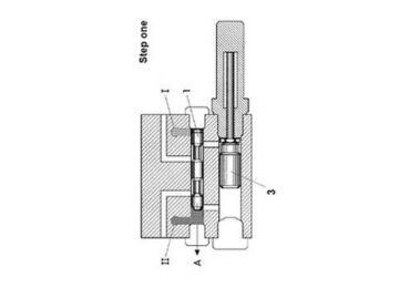
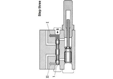
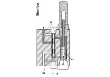
VSL Indicator
The advantage of the VSL blocks is that they are easily adjustable and can be used to witness the working situation through the indicated pin “G.”
You could turn the Screw “F” to adjust the the discharge.

VSL Working Process

What Is a DW Dual-Line Grease Block?
In a dual-line lubrication system, a pump pressurizes Line A while Line B vents (first half-cycle), then a reversing / change-over valve switches so Line B is pressurized and Line A vents (second half-cycle). Metering blocks such as DW sit along the main lines. They use alternating line pressure to move internal pistons and discharge grease to each lubrication point once per full A→B cycle.
The DW block is one of IsoHiTech’s dual-line grease metering options alongside VSG, VSL, and ZVB. It is rated for 20 MPa system pressure—appropriate when your pump station and main lines are sized for this class rather than 40 MPa heavy-industry blocks.
Where the DW Block Sits in the System
Typical dual-line grease layout:
- Grease pump station — manual, electric, or pneumatic (grease pump hub)
- Reversing valve — switches pressure between Line A and Line B (e.g. DR4-5 reversing valve)
- Main supply lines — high-pressure hose from pump header to blocks along the machine
- DW metering blocks — one block per zone, mounted near lubrication points
- Secondary lines — 1/4″ tubing or hose to each bearing / nipple (lubrication pipe)
If one lubrication point blocks, other outlets on the same dual-line architecture continue to receive grease—a key reason dual-line systems are used in mining, cement, steel, and other continuous-process plants.
DW vs. Other Dual-Line Metering Blocks
Use this table to pick the correct block family (do not substitute progressive DJF blocks):
| Block | Max system pressure | Typical discharge/cyc | Outlets | Best when |
|---|---|---|---|---|
| DW (this page) | 20 MPa | 0.15–5.0 ml (adjustable) | 2 / 4 / 6 / 8 | 20 MPa pump systems, NLGI #3, cost-effective metering |
| ZVB (SSPQ-P) | 40 MPa | 0.5 / 1.5 / 3.0 ml fixed steps | 1–8 | High-pressure long-distance dual-line, modular valves |
| VSG | 40 MPa | 0–2.2 ml adjustable | 1–8 | Lincoln-compatible dual-line, visual cycle control |
| VSL | 400 bar class | 0–5 ml adjustable | 2–8 | High-pressure dual-line with indicator pin monitoring |
DW vs. progressive grease manifold: Progressive blocks (DJF, SSV, IHI) use sequential piston sections on one supply line. DW blocks require two alternating main lines and a reversing valve—they are not interchangeable. See grease manifold block for progressive systems only.
How to Select a DW Block (5 Steps)
Step 1 — Confirm dual-line architecture. Verify pump, reversing valve, and control logic are dual-line—not single-line SLR or progressive.
Step 2 — Match pump pressure class. DW is for 20 MPa rated systems. If your pump and lines are designed for 40 MPa and long main-line runs, evaluate ZVB or VSL instead.
Step 3 — Choose discharge series. Pick the P.N. family by required ml/cyc at each outlet:
- DW-2xH (e.g. DW-22H … DW-28H): 0.15–0.6 ml/cyc — small bearings, light dose
- DW-3xH (DW-32H … DW-38H): 0.2–1.2 ml/cyc — general industrial
- DW-4xH (DW-42H … DW-48H): 0.6–2.5 ml/cyc — medium bearings
- DW-5xH (DW-52H … DW-58H): 1.2–5.0 ml/cyc — high grease demand points
Step 4 — Select outlet count. Order 2, 4, 6, or 8 outlets to match the number of points served by that block (last digit of P.N.: DW-24H = 4 outlets).
Step 5 — Set adjustment and verify cycles. Turn the adjustment screw to target discharge within the listed range; confirm indicator pin movement each half-cycle after system purge. Send point list and tubing lengths to IsoHiTech for BOM confirmation.
Installation & Troubleshooting
- Mount DW blocks where the indicator pin and adjustment screw are accessible for inspection.
- Purge each new outlet line before connecting to bearings—air causes false “no delivery” symptoms.
- Use grease NLGI #3 or softer; stiffer grease may not meter reliably at 20 MPa if lines are long or cold.
- One outlet dry, others OK: inspect secondary line, fitting, or blocked nipple—not necessarily the whole block.
- No indicator movement on any outlet: check reversing valve operation, pump pressure on active line, and inlet 3/8″ connection.
- Progressive system stall symptoms on a dual-line plant: wrong block type installed—verify architecture before replacing DW.
Related Guides
- Dual-line lubrication systems: engineering guide
- Dual-line lubrication systems hub
- Grease pump selection
- Automatic lubrication overview
- Grease distributor block (progressive hub)
Before you buy: read our central lubrication system guide.
A DW block meters grease in a dual-line centralized lubrication system. It mounts on the alternating main supply lines and delivers a set volume to each outlet every full pressure cycle. Use DW blocks when you need adjustable dual-line metering at 20 MPa with 2, 4, 6, or 8 outlets per block.
Choose by required ml per cycle at each lubrication point: DW-2xH for 0.15–0.6 ml/cyc, DW-3xH for 0.2–1.2 ml/cyc, DW-4xH for 0.6–2.5 ml/cyc, DW-5xH for 1.2–5.0 ml/cyc. Then pick the last model digit for outlet count (e.g. DW-26H = 6 outlets in the 0.15–0.6 ml series).
Yes. DW blocks are rated for grease up to NLGI #3. Ensure pump, lines, and ambient temperature allow the grease to flow at 20 MPa. In cold climates or long secondary lines, softer grades (NLGI #1 or #2) may improve reliability.
DW blocks work only in dual-line systems with two alternating main lines and a reversing valve. Progressive manifold blocks (DJF, SSV, IHI) use one supply line and sequential sections—one blocked point can stop the whole progressive chain. The architectures are not interchangeable. See grease manifold block for progressive selection.
Turn the adjustment screw on the block to increase or decrease stroke volume within the listed range for your series. Each series has a defined ml per turn (0.04, 0.06, 0.10, or 0.15 ml). After adjustment, run several full dual-line cycles and measure grease collected at an outlet, or verify consistent movement of the indicator pin each half-cycle.
First inspect the secondary line and fitting to that point for kinks, leaks, or a blocked nipple. If other outlets on the same block cycle normally, the block is likely fine. If no outlets deliver and the indicator pin does not move, check reversing valve operation, pump output on the active main line, and inlet connection. Purge air from new lines before commissioning.