



Precision CNC Manufacturing Excellence
Advanced 5-axis CNC machining centers deliver ±0.02mm dimensional accuracy for complex hydraulic manifold blocks. Our precision drilling and cross-drilling capabilities create perfect internal passages for CETOP, ISO 4401, and NFPA standard valve interfaces. Every manifold undergoes CMM inspection to ensure leak-free valve mounting and optimal flow performance.
Premium Materials & Certified Quality
From lightweight aluminum 6061-T6 to high-strength steel 4140, we select optimal materials for your application requirements. All manifolds are pressure tested to 1.5× working pressure with complete material certifications and dimensional reports. ISO 9001:2015 certified manufacturing ensures consistent quality and traceability for every order.


Fast Turnaround & Expert Support
Rapid prototyping in 2-3 weeks, production quantities in 4-6 weeks. Same-day quotes for standard configurations. Our application engineers provide free technical consultation, CAD design services, and material selection guidance. From concept to delivery, we ensure your hydraulic system meets performance requirements on time.
Custom Solutions & Global Reach
Whether you need single prototypes or volume production, we deliver cost-effective custom hydraulic manifold blocks tailored to your specifications. Supporting pressures from 210 to 420 bar, flow rates up to 300 L/min, with global shipping and competitive pricing. Partner with us for reliable, long-term hydraulic component supply.


The die-casting central manifolds are safe. They have many ports and mounting options. They work with Target Hydraulics’ plastic and steel tanks. They are for the North American and European markets for hydraulic power pack units.

The system combines a cartridge valve manifold and hydraulic cartridge valves. It is a hydraulic cartridge valve manifold system. It uses electrical components to control the speed and direction of hydraulic cylinders. The manifold block is the system’s central hub. It holds valves to maintain hydraulic oil pressure and flow direction.
Single Station Manifolds (4)

- Application: Independent control of single hydraulic cylinder
- Interface: CETOP 03, CETOP 05, D03, D05 patterns available
- Material Options: Aluminum 6061-T6, Steel 1045, Ductile Iron
- Port Configuration: P, T, A, B ports with standard threading
- Pressure Rating: 210-350 bar depending on material
- Typical Uses: Lift tables, dock levelers, single cylinder systems

- Valve Interface: ISO 4401-03 (CETOP 03) mounting pattern
- Flow Capacity: Up to 60 L/min (16 GPM)
- Port Threading: 3/8″ BSP or SAE -6 ports
- Dimensions: 80mm × 60mm × 40mm (aluminum)
- Weight: 0.8kg (aluminum) / 1.8kg (steel)
- Compatible Valves: All NG6 CETOP 03 valves

- Valve Interface: ISO 4401-05 (CETOP 05) mounting pattern
- Flow Capacity: Up to 120 L/min (32 GPM)
- Port Threading: 1/2″ BSP or SAE -8 ports
- Dimensions: 125mm × 80mm × 50mm
- Pressure Rating: 350 bar working pressure
- Applications: Industrial machinery, construction equipment

- Standard: NFPA D03 (North American standard)
- Thread Type: SAE J1926 straight thread or NPT
- Port Sizes: P,T (-8 ports), A,B (-6 ports)
- Pressure Rating: 5,000 PSI (345 bar)
- Valve Compatibility: Parker, Vickers, Eaton D03 valves
- Material: Aluminum or steel construction
Dual Station Manifolds (3)

- Configuration: 2 valve positions in parallel or series
- Flow Pattern: Independent A&B ports, common P&T supply
- Valve Spacing: Standard CETOP spacing between stations
- Applications: Twin cylinder systems, dual function control
- Port Arrangement: Side, rear, or bottom port configurations
- Custom Options: Relief valve integration, pilot pressure supply

- Interface: 2 × ISO 4401-03 valve positions
- Overall Dimensions: 160mm × 60mm × 40mm
- Flow Capacity: 120 L/min (32 GPM) total
- Port Configuration: Central P&T, individual A&B work ports
- Weight: 1.4kg (aluminum) / 3.2kg (steel)
- Applications: Mobile equipment, agricultural machinery

- Interface: 2 × ISO 4401-05 valve positions
- Flow Capacity: 240 L/min (63 GPM) total
- Port Sizes: 3/4″ BSP supply, 1/2″ BSP work ports
- Dimensions: 250mm × 80mm × 50mm
- Applications: Industrial presses, construction equipment
- Options: Priority valve integration, load sensing capability
Multi Station Manifolds (4)

- Configuration: 3 to 8 valve positions
- Flow Distribution: Parallel supply with individual control
- Modular Design: Expandable for future requirements
- Pressure Zones: Single or dual pressure supply options
- Applications: Complex automation, multiple actuator control
- Custom Engineering: Application-specific layouts available

- Interface: 4 × CETOP 03 or CETOP 05 positions
- Supply Method: Parallel distribution manifold
- Flow Capacity: 60 L/min per station (CETOP 03)
- Port Access: Rear-mounted work ports for easy connection
- Dimensions: 320mm × 60mm × 40mm (CETOP 03)
- Applications: Automated machinery, multi-cylinder systems

- Configuration: 6 valve positions with dual supply zones
- Zone Control: Independent pressure control per zone
- Flow Management: Optimized internal passage design
- Expansion: Field-expandable to additional stations
- Applications: Large industrial systems, production machinery

- Maximum Configuration: 8 valve positions
- Supply Strategy: Dual supply lines for optimal flow distribution
- Pressure Rating: 350 bar continuous duty
- Cooling: Heat dissipation design for continuous operation
- Applications: Heavy industrial automation, complex machinery
Manifolds with Relief Valve (3)

- Integrated Protection: Built-in pressure relief valve
- Relief Valve Type: Direct-operated, adjustable setting
- Pressure Range: 50-350 bar adjustment range
- Mounting: Cartridge-type relief valve installation
- Access: External adjustment knob for field setting
- Applications: Systems requiring overpressure protection

- Relief Integration: Cartridge relief valve cavity
- Flow Capacity: 120 L/min relief capacity
- Adjustment: External hex adjustment screw
- Port Connection: Relief valve return to tank
- Dimensions: 80mm × 60mm × 50mm
- Safety: Prevents system overpressure damage

- Protection: Individual or master relief valve options
- Configuration: Per-circuit or common relief protection
- Flow Rating: Sized for maximum system flow
- Monitoring: Pressure switch compatibility
- Installation: Integrated mounting, no external plumbing
Custom Hydraulic Manifolds (3)

- Design Service: Application-specific manifold design
- CAD Support: 3D modeling and flow analysis
- Prototype: Rapid prototyping for validation
- Material Selection: Optimal material for application
- Testing: Pressure and flow testing before delivery
- Applications: OEM equipment, specialized machinery

- Material: 6061-T6 aluminum alloy
- Machining: CNC precision manufacturing
- Surface Treatment: Anodizing, powder coating options
- Weight Optimization: Lightweight for mobile applications
- Pressure Rating: Up to 210 bar working pressure
- Applications: Aerospace, automotive, mobile equipment

- Material: 1045 or 4140 steel grades
- Pressure Capability: Up to 420 bar working pressure
- Heat Treatment: Stress relief and hardening available
- Surface Protection: Zinc plating, painting options
- Applications: Heavy industry, high-pressure systems
Cartridge Valve Manifolds (2)

- Valve Type: Screw-in cartridge valve compatibility
- Cavity Standards: Industry standard cavities (ICC)
- Flow Capacity: High flow with minimal pressure drop
- Modular Design: Stackable configuration options
- Applications: Industrial automation, mobile equipment
- Advantages: Compact design, easy maintenance

- Cartridge Sizes: 8mm, 10mm, 16mm, 25mm cavities
- Flow Rating: Up to 250 L/min per cartridge
- Pressure Rating: 350 bar standard, 420 bar optional
- Control: Manual, solenoid, or pilot operation
- Integration: Multiple cartridge functions in one block
Aluminum Manifold Blocks (2)

- Alloy: 6061-T6 aluminum for optimal strength
- Weight Savings: 60% lighter than steel equivalents
- Corrosion Resistance: Excellent in outdoor applications
- Machining: Excellent machinability for complex designs
- Anodizing: Hard anodize coating available
- Applications: Mobile equipment, aerospace, marine

- CNC Machining: Precision 5-axis manufacturing
- Tolerances: ±0.05mm dimensional accuracy
- Surface Finish: Ra 3.2μm standard, finer available
- Thread Quality: Class 2B threads, leak-free assembly
- Deburring: Complete burr removal for system cleanliness
- Testing: Pressure and dimensional verification
Steel Manifold Blocks (2)

- Material Grades: 1045, 4140, or stainless steel
- Pressure Capability: 350-500 bar working pressure
- Durability: Long service life in demanding applications
- Heat Treatment: Stress relief, hardening available
- Applications: Heavy construction, mining, industrial
- Surface Treatment: Zinc plating, painting, powder coating

- Material: 316 or 316L stainless steel
- Corrosion Resistance: Excellent for marine, chemical applications
- Pressure Rating: Up to 420 bar working pressure
- Passivation: Enhanced corrosion protection
- Applications: Marine, food processing, chemical industry
- Certifications: FDA compliant materials available
Hydraulic Valve Blocks (2)

- Function: Integrated valve and manifold assembly
- Valve Types: Directional, pressure, flow control valves
- Block Material: Aluminum, steel, or ductile iron
- Integration: Complete valve and manifold solution
- Customization: Application-specific valve combinations
- Testing: Complete functional testing before shipment

- Control Functions: Pressure, flow, direction control
- Valve Integration: Multiple valve functions in one block
- Pilot Control: Electronic or hydraulic pilot operation
- Feedback: Position and pressure feedback capability
- Applications: Automated systems, precision control
Mini Hydraulic Power Packs (2)

- Compact Design: All-in-one hydraulic power solution
- Flow Capacity: 1-15 L/min typical range
- Pressure Range: 70-210 bar operating pressure
- Tank Capacity: 1-20 liter reservoir options
- Applications: Small machinery, test equipment, tooling
- Power Options: Electric motor or manual operation

- Integration: Pump, motor, reservoir, manifold assembly
- Control: Manual or electric valve operation
- Mounting: Portable or fixed installation
- Cooling: Natural or forced air cooling
- Applications: Laboratory equipment, light industrial
Application-Specific Manifolds (4)
- Functions: Lift, tilt, side shift control
- Pressure Rating: 175-250 bar typical
- Valve Integration: Load holding, flow control valves
- Mounting: Mast or chassis mounting options
- Materials: Aluminum for weight reduction
- Safety Features: Integrated safety valves
- Control: Proportional control capability
- Pressure: 250-350 bar working pressure
- Functions: Boom lift, extend, rotate, platform level
- Certification: CE marking, ANSI compliance
- Operation: Raise, lower, extend lip functions
- Safety: Velocity fuses, relief valves
- Durability: Weather-resistant construction
- Mounting: Integrated with dock leveler frame
- Control: Push button or remote operation
- Functions: Clamp, bead break, lift operations
- Pressure: 10-15 bar pneumatic/hydraulic
- Compact: Space-saving design
- Control: Manual lever or foot pedal operation
- Safety: Integrated safety valves
Manufacturing Specifications (3)
- CNC Manufacturing: 3, 4, and 5-axis CNC machining
- Material Removal: Conventional and high-speed machining
- Tolerances: ±0.02mm achievable on critical dimensions
- Surface Quality: Ra 1.6μm on sealing surfaces
- Deburring: Complete internal passage deburring
- Testing: Pressure testing to 1.5× working pressure
- CAD Services: SolidWorks, AutoCAD design capability
- Flow Analysis: CFD simulation for optimization
- Stress Analysis: FEA verification of structural integrity
- Prototyping: Rapid prototype manufacturing
- Validation: Performance testing and verification
- ISO Certification: ISO 9001:2015 quality management
- Material Sourcing: Certified material suppliers
- Quality Control: CMM dimensional inspection
- Lead Times: 2-6 weeks depending on complexity
- Global Shipping: Worldwide delivery capability
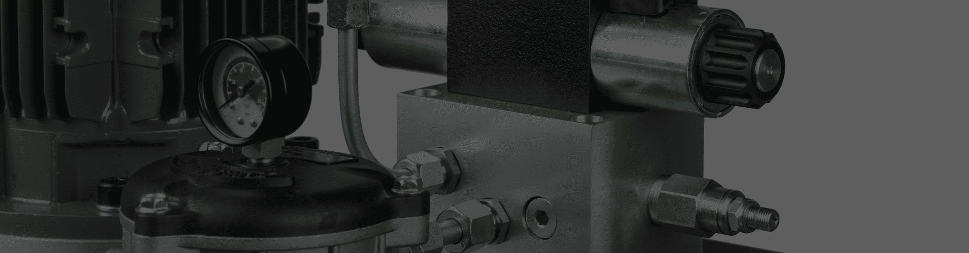
Understanding Hydraulic Manifold Blocks: Complete Guide
What is a Hydraulic Manifold Block?
A hydraulic manifold block is a precision-machined component that serves as the central distribution hub in hydraulic systems. Think of it as the electrical panel of your hydraulic system – it receives pressurized fluid from the pump and directs it to multiple circuits through strategically placed internal passages and valve mounting surfaces.
This critical component revolutionized hydraulic system design by eliminating the complex network of external pipes, fittings, and connections that were previously required to connect multiple valves. Instead of having individual valves scattered throughout the system with separate plumbing, the manifold block centralizes all valve functions into one compact unit. The internal passages are precisely machined using CNC technology to ensure consistent flow paths and minimal pressure losses.
Key Functions:
• Fluid Distribution: Routes hydraulic fluid to multiple actuators simultaneously, allowing for coordinated movement of different system components. This is essential in applications like excavators where boom, bucket, and swing functions must operate independently or together.
• Pressure Control: Integrates pressure relief and control valves in a compact design, providing system protection against overpressure while maintaining precise control over different circuits at varying pressure levels.
• System Integration: Consolidates multiple hydraulic functions into one unit, reducing the overall system footprint and improving reliability by minimizing potential leak points and connection failures.
• Space Optimization: Reduces the need for external piping and fittings by up to 70%, which is particularly valuable in mobile equipment where space and weight constraints are critical design factors.
Types of Hydraulic Manifold Blocks
Mono-block Manifolds
Best for: Simple applications with fixed valve configurations
Mono-block manifolds represent the most robust and reliable design in hydraulic systems. These manifolds are machined from a single piece of material, typically aluminum or steel, creating an extremely strong foundation for high-pressure applications. The manufacturing process involves complex CNC machining operations where internal passages are drilled and cross-drilled to create the required flow paths. Since there are no joints or connections within the block itself, mono-block manifolds eliminate potential internal leak points and can handle pressures up to 10,000 PSI.
• Single piece construction for maximum strength and pressure capability
• Internal passages machined directly into the block using precision CNC equipment
• Ideal for high-pressure applications where system reliability is paramount
• Common in mobile equipment and construction machinery where vibration resistance is crucial
• Lower long-term maintenance costs due to robust construction and fewer wear points
Modular Manifold Systems
Best for: Complex systems requiring flexibility
Modular manifold systems offer unparalleled flexibility in hydraulic system design and maintenance. Each valve function is housed in its own separate section that bolts to adjacent sections, creating a customizable hydraulic control center. This design philosophy allows engineers to configure exactly the valve functions needed for each application without the expense of custom machining. The modular approach also means that individual valve sections can be replaced or upgraded without affecting the entire manifold assembly.
• Individual valve sections bolt together using standard mounting hardware and sealing systems
• Easy maintenance and valve replacement without system disassembly
• Expandable design allows for future modifications and system upgrades
• Popular in industrial automation where changing production requirements demand system flexibility
• Cost-effective for prototype development and systems requiring frequent reconfiguration
Laminar Manifolds
Best for: High-flow, low-pressure applications
Laminar manifolds utilize a unique flat-plate construction method that sandwiches flow control layers between sealing plates. This design excels in applications requiring high flow rates at relatively low pressures, typically under 3,000 PSI. The flat construction allows for very large flow passages and smooth flow paths, minimizing pressure drop across the manifold. Each layer in the stack serves a specific function – flow control, pressure regulation, or structural support.
• Flat plate construction with O-ring sealing between layers for easy serviceability
• Quick assembly and disassembly makes them ideal for testing and development applications
• Excellent for systems requiring frequent reconfiguration or valve function changes
• Commonly used in testing facilities, hydraulic research, and prototype development
• Lower manufacturing costs for complex flow patterns compared to drilled manifolds
Material Selection Guide
Aluminum Manifold Blocks
Pressure Range: Up to 3,000 PSI
Aluminum manifold blocks have become increasingly popular in mobile hydraulic applications due to their excellent strength-to-weight ratio and superior corrosion resistance. The most commonly used aluminum alloy for hydraulic manifolds is 6061-T6, which provides excellent machinability while maintaining sufficient strength for medium-pressure applications. The lightweight nature of aluminum makes it particularly valuable in mobile equipment where weight reduction directly impacts fuel efficiency and payload capacity.
Advantages:
• Lightweight construction reduces overall system weight by 30-40% compared to steel
• Excellent corrosion resistance, especially in marine and outdoor applications
• Cost-effective manufacturing for medium-pressure systems due to easy machinability
• Superior thermal conductivity helps dissipate heat generated by hydraulic valves
• Easy machining allows for complex internal passages and intricate valve mounting patterns
Best Applications: Agricultural tractors, material handling equipment, aerial work platforms, light construction machinery, and any mobile application where weight is a critical design factor
Steel Manifold Blocks
Pressure Range: 5,000+ PSI
Steel manifold blocks represent the gold standard for high-pressure hydraulic applications where maximum strength and durability are required. Common steel grades include 1045 for moderate pressure applications and 4140 for extreme high-pressure systems. Steel manifolds can withstand the intense pressures found in heavy construction equipment, industrial presses, and marine applications where failure is not an option.
Advantages:
• Maximum strength capabilities for high-pressure systems up to 10,000+ PSI
• Superior durability in harsh operating environments with extreme temperature variations
• Extended service life in demanding applications with high-cycle operations
• Excellent fatigue resistance under repeated pressure cycling
• Can accommodate larger valve sizes without compromising structural integrity
Best Applications: Heavy construction equipment (excavators, bulldozers), industrial hydraulic presses, marine deck equipment, mining machinery, and stationary high-pressure power units
Ductile Iron Manifold Blocks
Pressure Range: Up to 5,000 PSI
Ductile iron manifold blocks offer an excellent compromise between strength, weight, and cost for industrial applications. This material provides superior strength compared to aluminum while remaining more cost-effective than steel for large manifold blocks. Ductile iron’s unique metallurgical structure combines the castability of traditional iron with enhanced ductility and impact resistance.
Advantages:
• Optimal strength-to-weight ratio for stationary industrial applications
• Cost-effective solution for high-pressure applications where weight is not critical
• Excellent machinability allows for precise internal passage creation
• Good vibration dampening characteristics reduce system noise
• Moderate corrosion resistance suitable for indoor industrial environments
Best Applications: Stationary industrial equipment, hydraulic power units for manufacturing, plastic injection molding machines, hydraulic presses, and fixed installation systems where weight is not a primary concern
How Does a Hydraulic Manifold Work?
The hydraulic manifold block operates on the principle of controlled fluid distribution, serving as the central nervous system of complex hydraulic machinery. Understanding how these systems work is crucial for proper system design, troubleshooting, and maintenance. The manifold’s operation involves precise fluid routing through a network of internal passages that have been strategically designed and machined to optimize flow patterns and minimize pressure losses.
Here’s the detailed step-by-step process:
1. Inlet Flow
Pressurized hydraulic fluid enters through the main supply port, which is typically the largest port on the manifold and connects directly to the hydraulic pump output. The inlet design often includes internal chamfers and smooth transitions to minimize turbulence as high-pressure fluid enters the distribution network.
2. Internal Routing
Machined passages direct fluid to individual valve mounting surfaces through a complex network of intersecting channels. These passages are precisely sized to maintain optimal flow velocities (typically 15-20 ft/sec) while providing adequate pressure to each valve station. The passage layout requires careful engineering to avoid stress concentrations and ensure adequate wall thickness.
3. Valve Control
Mounted valves control flow, pressure, and direction to each circuit based on operator input or automated control signals. Each valve type (directional, pressure, flow control) performs its specific function while being supplied with hydraulic power through the manifold’s internal distribution system.
4. Output Distribution
Controlled fluid flows to cylinders, motors, or other actuators through work ports that are sized and positioned for each specific application. The manifold may include multiple pressure levels and return paths to accommodate different actuator requirements.
5. Return Path
Used fluid returns through dedicated return passages back to the reservoir, often at low pressure but potentially high flow rates. Return passages are typically larger than supply passages to accommodate the volume of returning fluid without creating back pressure.
Critical Design Elements:
• Cross-drilling: Intersecting passages that connect valve ports require precise angular orientation and proper intersection geometry to minimize pressure losses and avoid sharp edges that could cause turbulence
• Port sizing: Proper diameter selection based on flow requirements prevents excessive velocity that could cause pressure drop, noise, or erosion of internal surfaces
• Wall thickness: Adequate material between passages ensures structural integrity under pressure while allowing for thermal expansion and contraction
• Surface finish: Smooth internal passages (typically 125 RMS or better) reduce turbulence, minimize particle generation, and improve flow efficiency throughout the system
Hydraulic Manifold Block Design Considerations
Pressure Drop Optimization
Pressure drop across a hydraulic manifold directly impacts system efficiency, heat generation, and overall performance. Each component in the hydraulic circuit contributes to total system pressure loss, and the manifold block’s internal design plays a crucial role in minimizing these losses. Excessive pressure drop not only reduces available pressure at actuators but also generates unwanted heat that must be dissipated by the hydraulic cooling system.
• Rule of thumb: Keep passage velocity under 20 ft/sec for efficiency, with 15 ft/sec being optimal for most applications. Higher velocities increase pressure drop exponentially and can cause erosion of internal surfaces over time.
• Port sizing: Use larger ports for high-flow applications, following industry standards such as SAE J1926 for straight thread ports or ISO 6149 for metric applications. Undersized ports are a common cause of system inefficiency.
• Bend radius: Minimize sharp corners in internal passages by using smooth, gradual transitions. Sharp 90-degree turns can cause significant pressure losses and create turbulence that generates noise and heat.
• Length calculation: Shorter passages reduce overall system pressure drop, but must be balanced against manufacturing constraints and structural requirements for adequate wall thickness between passages.
Valve Integration Strategy
The success of any hydraulic manifold design depends heavily on how well it integrates with the valves that control system functions. This integration involves both mechanical mounting considerations and hydraulic performance optimization. Poor valve integration can lead to maintenance difficulties, performance issues, and premature component failure.
• CETOP mounting: Standard ISO 4401 valve mounting patterns ensure compatibility with a wide range of valve manufacturers and facilitate future valve upgrades or replacements. These standardized patterns include specific bolt hole locations, port arrangements, and sealing surface requirements.
• SAE ports: Common thread standards for North American applications, including SAE J1926 straight thread and SAE J1453 37-degree flare fittings. Proper thread engagement and sealing methods are critical for leak-free operation.
• Custom interfaces: Specialized mounting arrangements for proprietary valves or unique application requirements. Custom interfaces require careful coordination between manifold and valve manufacturers to ensure proper fit and performance.
• Service accessibility: Position frequently maintained valves for easy access during routine service operations. Consider the physical size of service tools and the space required for valve removal and installation when determining valve positions.
Common Hydraulic Manifold Applications
Construction Equipment
Construction equipment represents one of the most demanding applications for hydraulic manifold blocks, requiring systems that can operate reliably in harsh environments while providing precise control over multiple functions. These applications typically involve high pressures, high flow rates, and extreme duty cycles that test the limits of hydraulic component design.
• Excavators: Multi-function valve integration for boom, bucket, and swing operations requires sophisticated manifold designs that can handle simultaneous operation of multiple high-flow circuits. Modern excavator manifolds often integrate pilot pressure control, load sensing, and pressure compensation functions to optimize performance and fuel efficiency.
• Loaders: Steering and implement control systems demand compact manifold packages that can fit within tight machine envelopes while providing responsive control. Priority valve integration ensures steering function receives hydraulic power even when implement circuits are under heavy load.
• Cranes: Precise load control applications require manifold systems with integrated safety valves, counterbalance valves, and fine metering capabilities. These manifolds must maintain precise control even with varying loads and operating positions while providing fail-safe operation in case of hydraulic system failure.
Agricultural Machinery
Agricultural applications present unique challenges for hydraulic manifold design, including seasonal operation patterns, exposure to corrosive materials, and the need for cost-effective solutions that can withstand years of reliable operation. These systems often operate in dusty, wet conditions with temperature extremes that test component durability.
• Tractors: Implement control systems for multiple hydraulic functions including three-point hitch operation, power steering, and remote hydraulic outlets for implements. Modern tractor manifolds integrate electronic control capabilities for precision agriculture applications and automated implement control.
• Harvesters: Header and drive system integration requires manifolds that can coordinate complex cutting, conveying, and cleaning functions. These systems often include variable displacement pump control and load sensing capabilities to optimize performance across different crop conditions.
• Irrigation: Automated valve control for water distribution systems utilizes manifold blocks to control multiple irrigation zones from a central location. These applications require corrosion-resistant materials and reliable sealing systems to handle water-based fluids and outdoor environments.
Industrial Applications
Industrial hydraulic manifolds serve in some of the most sophisticated automated manufacturing systems, where precision, reliability, and integration capabilities are paramount. These applications often require custom-designed manifolds that can interface with complex control systems and provide repeatable performance over millions of operating cycles.
• Manufacturing: Automated assembly line control systems use manifold blocks to coordinate multiple actuators in precise sequences. These manifolds often integrate pressure, flow, and position feedback systems to ensure accurate and repeatable operations in high-volume production environments.
• Material Handling: Conveyor and lift system integration requires manifolds that can control multiple elevation and positioning functions while maintaining smooth, coordinated motion. Safety considerations are paramount in these applications, requiring integrated pressure relief and emergency stop capabilities.
• Process Control: Automated valve sequencing in production lines utilizes programmable manifold systems that can adapt to different product configurations and production requirements. These systems often integrate with plant-wide control networks for coordinated operation and data collection.
Hydraulic Manifold Block Troubleshooting
Common Problems and Solutions
Effective troubleshooting of hydraulic manifold blocks requires a systematic approach that considers both hydraulic principles and mechanical factors. Many manifold-related problems are actually symptoms of issues elsewhere in the system, making proper diagnosis crucial for effective repairs and preventing recurring failures.
🔧 Problem: Excessive Pressure Drop
• Cause: Undersized passages, ports, or contamination restricting flow paths. This can result from original design limitations, manufacturing defects, or gradual buildup of contamination over time.
• Solution: Analyze system flow requirements and compare to manifold specifications. If passages are undersized, consider flow rate reduction or manifold redesign. Clean internal passages if contamination is suspected, and implement improved filtration to prevent recurrence.
• Prevention: Specify adequate passage sizes during initial design phase and maintain proper fluid cleanliness levels throughout system operation.
🔧 Problem: Internal Leakage
• Cause: Worn valve seats, damaged O-rings, or improper valve installation causing cross-port leakage within the manifold. This often develops gradually and may not be immediately apparent but can significantly impact system performance.
• Solution: Perform systematic valve-by-valve testing to isolate the source of internal leakage. Replace worn sealing components and inspect mounting surfaces for damage. Verify proper valve installation procedures and torque specifications.
• Prevention: Follow recommended maintenance schedules for valve overhaul, maintain proper fluid cleanliness, and avoid over-tightening valve mounting bolts.
🔧 Problem: External Leakage
• Cause: Damaged mounting surfaces, improper gasket installation, or incorrect bolt torque allowing pressurized fluid to escape at manifold interfaces.
• Solution: Remove and inspect all sealing surfaces for scratches, corrosion, or warpage. Re-machine surfaces if necessary and replace all sealing elements. Follow proper assembly procedures including correct torque sequence and values.
• Prevention: Use proper installation procedures, store sealing elements properly to prevent damage, and avoid over-torquing which can distort sealing surfaces.
🔧 Problem: Valve Interference
• Cause: Inadequate spacing between valve mounting positions prevents proper valve installation or interferes with maintenance access.
• Solution: Evaluate manifold layout and valve envelope requirements. If interference cannot be resolved through different valve selection, manifold redesign may be necessary to provide adequate clearances.
• Prevention: Consider valve dimensions, electrical connector requirements, and maintenance tool access during manifold design phase.
Maintenance Best Practices
Regular Inspection Schedule
Proper maintenance of hydraulic manifold blocks is essential for system reliability, safety, and optimal performance. A systematic approach to inspection and maintenance can prevent costly failures and extend system life significantly. The inspection schedule should be tailored to the specific application, operating environment, and duty cycle of each system.
📅 Daily Inspections:
• Visual inspection for external leaks, unusual noises, or abnormal operating temperatures
• Check for signs of hydraulic fluid contamination such as discoloration, foaming, or unusual odors
• Verify that all pressure gauges and indicators are reading within normal operating ranges
📅 Weekly Inspections:
• Check mounting bolt torque on critical valves using a calibrated torque wrench, paying special attention to high-pressure circuits and frequently operated valves
• Inspect all flexible hydraulic lines for signs of wear, bulging, or degradation that could indicate impending failure
📅 Monthly Inspections:
• Monitor pressure drop across the manifold using precision pressure gauges at inlet and outlet ports
• Increasing pressure drop may indicate internal contamination, valve wear, or passage restriction that requires attention
📅 Annual Inspections:
• Complete system pressure test according to manufacturer specifications
• Valve calibration verification and comprehensive inspection of all manifold mounting surfaces
• Check for signs of wear, corrosion, or damage that could affect sealing performance
Preventive Maintenance
Preventive maintenance programs focus on addressing potential problems before they cause system failures or performance degradation. This proactive approach is particularly important for hydraulic manifold blocks due to their central role in system operation and the high cost of unplanned downtime.
🔬 Fluid Analysis:
• Regular oil sampling and laboratory analysis can detect contamination, additive depletion, and component wear products before they cause significant damage
• Implement sampling intervals based on system operating hours and environmental conditions, typically every 250-500 hours for mobile equipment
🔧 Filter Replacement:
• Maintain hydraulic fluid cleanliness according to ISO 4406 standards by replacing filters at recommended intervals
• Clean fluid is essential for valve operation and manifold longevity, as contamination can cause valve sticking, increased wear, and internal damage to precision-machined surfaces
⚙️ Torque Verification:
• Ensure proper bolt tension on valve mounting using manufacturer-specified torque values and sequences
• Improper torque can lead to gasket failure, manifold distortion, or valve misalignment that affects performance and reliability
🌡️ Temperature Monitoring:
• Install temperature sensors to monitor manifold block temperature and detect excessive heat buildup
• This could indicate restricted flow, valve malfunction, or inadequate cooling system capacity
• Operating temperatures should typically remain below 180°F (82°C) for optimal component life
Standard Hydraulic Manifold Specifications
Port Sizes and Standards
- SAE Straight Thread: -4, -6, -8, -10, -12, -16, -20, -24
- BSPP (British Standard): 1/8″, 1/4″, 3/8″, 1/2″, 3/4″, 1″
- Metric Thread: M10x1, M12x1.5, M14x1.5, M16x1.5, M18x1.5
Pressure Ratings by Material
- Aluminum 6061-T6: Up to 3,000 PSI working pressure
- Steel 1045: Up to 5,000 PSI working pressure
- Steel 4140: Up to 10,000 PSI working pressure
- Stainless Steel 316: Up to 6,000 PSI with corrosion resistance
Frequently Asked Questions
❓ Q: What’s the difference between a manifold block and a valve stack?
A: A manifold block has internal passages machined into a solid block of material, creating a compact and robust assembly with no external connections between valve functions. In contrast, a valve stack uses individual valves connected through external piping, connecting plates, or tie-rod assemblies. Manifold blocks offer superior reliability and compact packaging but are less flexible for system modifications. Valve stacks provide easier maintenance access and reconfiguration capabilities but require more space and have more potential leak points.
❓ Q: How do I calculate the wall thickness needed for my application?
A: Wall thickness calculation involves several factors including operating pressure, material properties, safety factors, and stress concentration effects. The basic formula is:
Wall thickness = (Pressure × Port diameter) / (2 × Material yield strength × Safety factor)
However, this simplified calculation doesn’t account for stress concentrations around intersecting passages or dynamic loading effects. For high-pressure applications above 3,000 PSI, consult with qualified hydraulic engineers and consider finite element analysis to ensure adequate safety margins.
❓ Q: Can I modify an existing manifold block?
A: Limited modifications are possible, but adding new passages or enlarging existing ones requires careful structural analysis. New cross-drilling can create stress concentration points that weaken the overall structure, particularly if the new passages intersect existing ones at acute angles. Surface mounting of additional valves is generally safer than internal modifications. Any significant modifications should be analyzed by qualified engineers and may require pressure testing to verify structural integrity.
❓ Q: What causes manifold block failure?
A: Manifold block failures typically result from one or more of the following causes:
• Fatigue cracking from repeated pressure cycling, especially in applications with frequent start-stop operations
• Corrosion from contaminated hydraulic fluid or exposure to corrosive environments
• Stress concentration from poor passage design or manufacturing defects
• Over-pressurization beyond design limits
• Thermal stress from extreme temperature variations
Proper design, material selection, and maintenance practices can prevent most failure modes.
❓ Q: How long should a hydraulic manifold last?
A: With proper design, manufacturing, and maintenance, quality hydraulic manifolds can operate reliably for 20+ years in most applications. Service life depends heavily on operating conditions including:
• Pressure cycling frequency
• Hydraulic fluid cleanliness
• Operating temperature ranges
• Environmental factors
Mobile equipment typically experiences shorter service life (10-15 years) due to vibration and harsh operating conditions, while stationary industrial applications may exceed 25 years of service life. Regular maintenance and monitoring can significantly extend manifold life and provide early warning of potential problems.
Custom vs. Standard Manifold Selection
Choose Standard Manifolds When:
- Application matches existing designs
- Lower initial cost is priority
- Shorter delivery time needed
- Simple valve configuration required
Choose Custom Manifolds When:
- Unique space constraints exist
- Specialized valve integration needed
- Optimized performance is critical
- Long-term production volumes justify tooling costs
Next Steps for Your Hydraulic System
When selecting a hydraulic manifold block for your application, consider these key factors:
- System pressure requirements and safety margins
- Flow rates and pressure drop limitations
- Valve types and mounting patterns needed
- Environmental conditions and material compatibility
- Maintenance accessibility and service requirements
For complex applications or high-pressure systems, consult with hydraulic engineers to ensure optimal manifold design and reliable operation.
Related lubrication resources
Centralized lubrication · Grease pump hub · Heavy equipment lubrication
Before you buy: read our guide to how distributor blocks work.
Frequently Asked Questions
Pressure Rating Comparison Chart
| Material Type | Maximum Working Pressure | Burst Pressure | Temperature Range | Best Applications |
|---|---|---|---|---|
| Aluminum 6061-T6 | 3,000 PSI | 12,000 PSI | -65°F to +250°F | Mobile equipment, aerial platforms |
| Steel 1045 | 5,000 PSI | 20,000 PSI | -40°F to +300°F | Industrial machinery, presses |
| Steel 4140 | 10,000 PSI | 40,000 PSI | -40°F to +350°F | Heavy construction, mining equipment |
| Ductile Iron | 5,000 PSI | 20,000 PSI | -20°F to +300°F | Stationary power units |
| Stainless 316 | 6,000 PSI | 24,000 PSI | -100°F to +400°F | Marine, food processing |
Port Size & Flow Capacity Guide
🔧 SAE Straight Thread Ports:
- -4 (1/4″): Up to 5 GPM – Small actuators, pilot circuits
- -6 (3/8″): Up to 15 GPM – Medium cylinders, motors
- -8 (1/2″): Up to 25 GPM – Standard hydraulic circuits
- -10 (5/8″): Up to 40 GPM – Large cylinders, high-flow applications
- -12 (3/4″): Up to 60 GPM – Heavy equipment main supply
- -16 (1″): Up to 100 GPM – Industrial power units
🔧 Metric Thread Ports:
- M10×1: Up to 8 GPM – European mobile equipment
- M14×1.5: Up to 20 GPM – Standard metric applications
- M18×1.5: Up to 45 GPM – High-flow metric systems
- M22×1.5: Up to 70 GPM – Large metric power units
Valve Mounting Pattern Standards
📐 ISO 4401 (CETOP) Mounting:
- NG06: 157mm × 92mm mounting pattern – Up to 60 L/min
- NG10: 210mm × 125mm mounting pattern – Up to 120 L/min
- NG16: 280mm × 175mm mounting pattern – Up to 250 L/min
- NG25: 350mm × 210mm mounting pattern – Up to 500 L/min
Construction Equipment Applications
🚜 Excavators & Track Loaders
Pressure Requirements: 4,000-6,000 PSI
Key Features: Multi-function integration, pilot pressure control, load sensing
- Boom/Bucket Control: Synchronized operation with pressure compensation
- Swing Motor Integration: High-torque applications requiring precise control
- Auxiliary Hydraulics: Multiple work tool connections with independent control
- Travel Drive: Hydrostatic transmission integration for smooth operation
Common Manifold Configuration: • Main relief valve: 4,500 PSI setting with adjustable pilot control • Load sensing pump: Variable displacement with pressure/flow compensation
• Pilot pressure supply: 350 PSI dedicated circuit for joystick controls • Return filtration: Integrated 10-micron return filter mounting
🏗️ Mobile Cranes & Aerial Equipment
Pressure Requirements: 3,000-5,000 PSI Key Features: Counterbalance valves, emergency lowering, precise load control
- Load Block Control: Anti-cavitation valves prevent load dropping
- Boom Extension: Telescopic cylinder control with synchronized operation
- Outrigger System: Individual leg control with pressure monitoring
- Swing Brake: Integrated parking brake valve for secure positioning
Safety Integration: • Emergency lowering: Manual override valves for power loss situations • Overload protection: Pressure switches with visual/audible alarms • Load moment: Integration with crane computer systems • Counterbalance valves: Prevent uncontrolled descent under all conditions
Agricultural Machinery Applications
🚜 Tractors & Utility Vehicles
Pressure Requirements: 2,500-3,500 PSI Key Features: Three-point hitch, PTO control, remote outlets
- Three-Point Hitch: Position and draft control with feedback sensors
- Front Loader: Quick-attach hydraulics with auxiliary functions
- Remote Outlets: Multiple quick-disconnect couplers for implements
- Power Steering: Priority valve ensures steering response under load
Agricultural-Specific Requirements: • Corrosion resistance: Zinc plating or anodized aluminum for weather protection • Serviceability: Easy access for field maintenance and repairs • Filtration: 25-micron filtration minimum for dusty environments
• Temperature range: -20°F to +150°F for seasonal operation
🌾 Harvesters & Specialty Equipment
Pressure Requirements: 3,000-4,500 PSI Key Features: Variable speed drives, header control, cleaning systems
- Header Drive: Variable displacement motors with speed control
- Cleaning Fan: Variable speed control for different crop conditions
- Grain Tank: Hydraulic unloading auger with position feedback
- Steering Assist: Load sensing power steering with manual backup
Industrial Automation Applications
🏭 Manufacturing & Assembly Lines
Pressure Requirements: 1,500-3,000 PSI Key Features: Precise positioning, rapid cycling, integration with PLCs
- Clamping Systems: High-force cylinders with position monitoring
- Part Transfer: Pneumatic over hydraulic intensifiers for rapid movement
- Press Operations: Programmable force and position control
- Safety Systems: Light curtain integration with emergency stop valves
Automation Integration: • Servo valve control: High-response valves for precise positioning • Pressure feedback: Real-time monitoring for quality control • PLC interface: Digital communication for automated operation • Data logging: Production monitoring and preventive maintenance scheduling
⚙️ Material Handling & Packaging
Pressure Requirements: 2,000-3,500 PSI
Key Features: Smooth operation, energy efficiency, minimal maintenance
- Conveyor Drives: Variable speed control for different products
- Lift Tables: Safety velocity fuses prevent uncontrolled descent
- Rotating Equipment: Hydraulic motor drives for consistent operation
- Palletizing: Precise positioning with force limiting for product protection
Pressure Drop Calculator Guide
📊 Calculating Manifold Pressure Drop:
Basic Formula:
ΔP = (Q² × L × ρ) / (2 × d⁵ × Cd²)
Where:
- ΔP = Pressure drop (PSI)
- Q = Flow rate (GPM)
- L = Passage length (inches)
- ρ = Fluid density (specific gravity)
- d = Passage diameter (inches)
- Cd = Discharge coefficient (typically 0.6-0.8)
💡 Quick Reference Chart:
| Flow Rate (GPM) | Passage Diameter | Estimated Pressure Drop |
|---|---|---|
| 10 GPM | 0.25″ (1/4″) | 15-25 PSI |
| 20 GPM | 0.375″ (3/8″) | 20-35 PSI |
| 30 GPM | 0.5″ (1/2″) | 25-40 PSI |
| 50 GPM | 0.625″ (5/8″) | 30-50 PSI |
Wall Thickness Design Calculator
🔧 Minimum Wall Thickness Formula:
t = (P × D) / (2 × S × E - P)
Where:
- t = Minimum wall thickness (inches)
- P = Working pressure (PSI)
- D = Port diameter (inches)
- S = Material allowable stress (PSI)
- E = Joint efficiency (typically 1.0 for solid blocks)
Material Allowable Stress Values:
- Aluminum 6061-T6: 35,000 PSI
- Steel 1045: 60,000 PSI
- Steel 4140: 95,000 PSI
- Ductile Iron: 45,000 PSI
Flow Velocity Guidelines
⚡ Recommended Velocities:
- Supply lines: 15-20 ft/sec maximum
- Return lines: 10-15 ft/sec maximum
- Suction lines: 4-8 ft/sec maximum
- Pilot lines: 5-10 ft/sec maximum
Velocity Calculation:
V = (Q × 0.408) / A
Where:
- V = Velocity (ft/sec)
- Q = Flow rate (GPM)
- A = Cross-sectional area (square inches)
Diagnostic Flow Chart
🔍 Problem: System Operates Slowly
Step 1: Check system pressure
- Normal pressure → Go to Step 2
- Low pressure → Check pump, relief valve setting
Step 2: Check flow rate
- Normal flow → Check actuator condition
- Low flow → Check for internal leakage in manifold
Step 3: Check fluid temperature
- Normal temp (120-160°F) → Check valve response time
- High temp (>180°F) → Check cooling system, pressure drops
Common Problem Solutions
🔧 Problem: External Leakage at Valve Interface
Immediate Actions:
- Stop operation and depressurize system safely
- Inspect O-ring sealing surfaces for damage
- Check torque values on valve mounting bolts
- Replace damaged seals using proper installation tools
Root Cause Analysis: • Over-torquing: Can compress O-rings excessively or distort manifold surface • Under-torquing: Allows movement and seal damage during operation • Surface damage: Scratches from improper installation or contamination • Wrong seal material: Chemical incompatibility with hydraulic fluid
Prevention: • Use calibrated torque wrench with manufacturer specifications • Inspect seals before installation for nicks or contamination
• Clean mounting surfaces with lint-free cloth and approved solvent • Follow proper sequence when tightening multiple bolts
🔧 Problem: Internal Cross-Port Leakage
Diagnostic Steps:
- Isolate each valve circuit individually
- Pressure test each circuit with gauge block
- Measure leakage rate across valve ports
- Compare to manufacturer specifications
Typical Leakage Rates:
- Directional valves: <5 drops/minute at rated pressure
- Pressure valves: <10 cc/minute at 100 PSI below setting
- Flow control valves: <2% of rated flow
Repair Actions: • Replace valve cartridges showing excessive leakage • Inspect manifold passages for contamination buildup • Flush system with clean hydraulic fluid
• Install finer filtration to prevent future contamination
🔧 Problem: Excessive Heat Generation
Temperature Monitoring:
- Manifold surface: Should not exceed 160°F (71°C)
- Hydraulic fluid: Optimal range 100-140°F (38-60°C)
- Valve bodies: Maximum 180°F (82°C)
Heat Source Analysis: • Pressure drops: Calculate total system pressure loss • Internal leakage: Use thermal imaging to locate hot spots • Relief valve chattering: Check for proper adjustment and pilot drain • Undersized passages: Measure actual vs. required flow capacity
Cooling Solutions: • Increase reservoir size: Minimum 3-5 times pump output per minute • Add heat exchanger: Size for 25-50% above calculated heat load • Improve air circulation: Ensure adequate ventilation around manifold
• Reduce pressure drops: Enlarge passages or reduce system pressure
Preventive Maintenance Schedule
📅 Daily Operations (5 minutes): • Visual inspection for external leaks • Check fluid level in reservoir
• Monitor operating temperature with infrared thermometer • Listen for unusual noises during normal operation
📅 Weekly Maintenance (30 minutes): • Check filter condition and differential pressure
• Verify pressure gauge readings against system requirements • Inspect flexible hoses for signs of wear or bulging • Clean external surfaces to prevent contamination buildup
📅 Monthly Inspections (2 hours): • Torque verification on all valve mounting bolts • Pressure test all circuits to verify performance • Fluid analysis sample for contamination and condition • Document performance trends for predictive maintenance
📅 Annual Overhaul (8-16 hours): • Complete disassembly and cleaning of manifold block • Dimensional inspection of all sealing surfaces
• Replace all seals and gaskets regardless of apparent condition • Pressure test to 150% working pressure per ANSI standards
Design Process Overview
🎯 Phase 1: Requirements Analysis (1-2 weeks) Our engineering team works directly with your technical staff to understand:
• System specifications: Pressure, flow, temperature requirements • Space constraints: Available envelope and mounting considerations
• Valve integration: Specific valve types and mounting patterns required • Performance goals: Efficiency targets and operational requirements • Environmental conditions: Operating temperature, contamination levels
Deliverables:
- Detailed requirements specification document
- Preliminary concept sketches and layouts
- Material recommendations based on application
- Project timeline and milestone schedule
🎯 Phase 2: Concept Design (2-3 weeks)
Advanced CAD modeling and simulation to optimize performance:
• 3D modeling: Complete manifold geometry with internal passages • Flow analysis: CFD simulation to minimize pressure drops • Stress analysis: FEA verification of structural integrity
• Thermal analysis: Heat dissipation and temperature distribution
Deliverables:
- 3D CAD models in customer-preferred format
- Technical drawings with GD&T specifications
- Performance predictions for pressure drop and flow distribution
- Material specifications and supplier recommendations
🎯 Phase 3: Prototype Development (3-4 weeks) Rapid prototyping and testing to validate design:
• CNC machining: Precision manufacturing using 5-axis machining centers • Quality inspection: CMM verification of all critical dimensions • Pressure testing: Validation to 150% of working pressure • Performance testing: Flow, pressure drop, and temperature measurements
Deliverables:
- Functional prototype for customer testing
- Test report with performance data and recommendations
- Manufacturing drawings ready for production
- Quality control procedures and inspection criteria
Manufacturing Capabilities
🏭 Machining Equipment:
- 5-Axis CNC Centers: ±0.0002″ precision for complex geometries
- CNC Lathes: Up to 24″ diameter capacity
- Surface Grinders: Ra 32 finish capability
- Coordinate Measuring: Zeiss CMM with automated inspection
🔧 Materials Processing:
- Heat treatment: In-house stress relief and hardening
- Surface treatments: Anodizing, zinc plating, powder coating
- Testing facilities: Pressure testing to 15,000 PSI
- Quality certifications: ISO 9001:2015, AS9100D
📦 Production Capacity:
- Prototype quantities: 1-10 pieces in 2-3 weeks
- Small batch: 10-100 pieces in 4-6 weeks
- Production runs: 100+ pieces in 6-8 weeks
- Rush orders: Emergency delivery available with premium pricing
Design Optimization Services
⚡ Performance Enhancement: • Flow optimization: Internal passage geometry for minimum pressure drop • Weight reduction: Material removal analysis while maintaining strength • Valve integration: Custom mounting patterns for optimal valve placement • Thermal management: Heat sink integration and cooling passage design
💰 Cost Optimization: • Material selection: Alternative materials meeting performance requirements • Manufacturing optimization: DFM analysis to reduce machining time • Standardization: Common components across multiple manifold designs • Volume pricing: Quantity breaks and long-term supply agreements
🔧 Maintenance Optimization:
• Service access: Valve placement for easy maintenance • Modular design: Replaceable sections for wear components • Diagnostic ports: Test points for system troubleshooting • Documentation: Complete service manuals and training materials
CAD Library & Technical Drawings
📁 Standard Manifold Blocks:
- ISO 4401 Mounting Patterns: NG06, NG10, NG16, NG25 in multiple materials
- SAE Mounting Patterns: D03, D05, D07, D08 standard configurations
- Custom Valve Patterns: Proprietary mounting designs for OEM applications
- Modular Systems: Stackable sections with standard interconnections
Available Formats: • SolidWorks (.sldprt, .sldasm) – Native format with full parametric features • AutoCAD (.dwg, .dxf) – 2D drawings and 3D wireframe models
• STEP/IGES (.stp, .igs) – Universal 3D formats for all CAD systems • PDF Drawings (.pdf) – Printable technical drawings with dimensions
📁 Installation & Service Manuals:
- Assembly Instructions: Step-by-step procedures with torque specifications
- O-Ring Installation: Proper techniques and seal compatibility charts
- Pressure Testing: Procedures for field testing and troubleshooting
- Maintenance Schedules: Recommended service intervals and procedures
Technical Specification Sheets
📊 Material Property Data:
- Mechanical Properties: Tensile strength, yield strength, hardness values
- Chemical Compatibility: Fluid compatibility charts for seals and materials
- Temperature Performance: Thermal expansion coefficients and operating limits
- Pressure Ratings: Working pressure, burst pressure, fatigue life data
📊 Performance Data:
- Flow Coefficients: Cv values for standard port sizes and passages
- Pressure Drop Charts: Flow vs. pressure drop for various configurations
- Response Time Data: Valve actuation times and system response characteristics
- Efficiency Curves: Overall system efficiency vs. operating conditions
Quality Certifications & Test Reports
🏆 Manufacturing Certifications:
- ISO 9001:2015: Quality management system certification
- AS9100D: Aerospace quality management standard
- IATF 16949: Automotive quality management certification
- CE Marking: European conformity for applicable products
🧪 Material Certifications:
- Mill Test Certificates: Chemical composition and mechanical properties
- Material Traceability: Complete chain of custody documentation
- NACE Compliance: Corrosion resistance for oil & gas applications
- RoHS Compliance: Environmental safety and material restrictions
📋 Test Reports:
- Pressure Testing: Hydrostatic testing to ANSI/NFPA standards
- Fatigue Testing: Cycle life testing for high-frequency applications
- Temperature Testing: Performance verification across operating range
- Vibration Testing: MIL-STD-810 compliance for mobile applications
Software Tools & Calculators
💻 Online Design Tools:
- Pressure Drop Calculator: Interactive tool for passage sizing
- Material Selection Guide: Decision tree for optimal material choice
- Cost Estimation Tool: Preliminary pricing for custom manifolds
- Lead Time Calculator: Delivery estimates based on configuration complexity
📱 Mobile Apps:
- Field Service App: Troubleshooting guide with diagnostic flowcharts
- Torque Reference: Proper torque values for all valve types and sizes
- Fluid Compatibility: Quick reference for seal and material selection
- Parts Ordering: Direct ordering of replacement seals and components
Construction Equipment Success
🏗️ Case Study: Major Excavator Manufacturer
Challenge: Weight reduction while maintaining 6,000 PSI capability Solution: Custom aluminum manifold with optimized internal passages Results: • 35% weight reduction compared to previous steel design • 15% improvement in fuel efficiency due to reduced machine weight
• Zero warranty issues after 18 months and 500+ units in field • $2.3M annual savings in reduced shipping costs and improved performance
“IsoHiTech’s engineering team delivered exactly what we needed – a manifold that reduced weight without compromising performance. Their testing and validation process gave us complete confidence in the design.”
– Chief Engineer, Global Construction Equipment OEM
🚜 Case Study: Agricultural Equipment Manufacturer Challenge: Corrosion resistance for fertilizer spreader applications
Solution: Stainless steel manifold with specialized coatings Results: • 300% increase in service life in corrosive environments • 90% reduction in warranty claims related to corrosion • $1.8M savings in warranty costs over 3-year period
• Customer satisfaction improved from 78% to 96%
Industrial Automation Success
⚙️ Case Study: Automotive Assembly Line Challenge: Precise positioning for robotic welding stations Solution: Servo-controlled manifold with integrated feedback Results: • ±0.1mm positioning accuracy achieved consistently
• 45% reduction in cycle time through optimized valve response • 99.8% uptime maintained over 12-month production period • $3.2M productivity gain from reduced downtime and faster cycles
“The integration capabilities and precise control we achieved with IsoHiTech’s manifold system transformed our production line efficiency.” – Manufacturing Engineering Manager, Automotive Tier 1 Supplier
Quality Certifications & Awards
🏆 Industry Recognition:
- Supplier of the Year 2023: Leading Construction Equipment Manufacturer
- Innovation Award 2022: International Fluid Power Society
- Quality Excellence: Zero defect delivery for 24 consecutive months
- Environmental Leadership: ISO 14001 certification for sustainable manufacturing
🔒 Security & Compliance:
- ITAR Registration: US State Department approval for defense applications
- Export Controls: Full compliance with international trade regulations
- Cybersecurity: SOC 2 Type II certification for data protection
- Supply Chain: Conflict minerals compliance and ethical sourcing
📊 Performance Metrics:
- 99.7% on-time delivery rate maintained over 5-year period
- 0.02% defect rate based on independent third-party audits
- 24-hour response time for technical support requests
- 98% customer retention rate among repeat customers
Partnership Program Benefits
🤝 Preferred Partner Advantages: • Priority scheduling for urgent orders and prototype development • Extended warranty: Up to 5 years on qualified applications
• Technical support: Dedicated engineering liaison for ongoing projects • Volume pricing: Graduated discounts based on annual purchase commitments
📈 Joint Development Opportunities: • Co-engineering programs for next-generation products • IP sharing: Mutual licensing agreements for innovative technologies • Market expansion: Joint marketing for new application areas
• Training programs: Technical education for customer engineering teams
🎯 Customer Support Services: • 24/7 technical hotline: Emergency support for critical applications • Field service: On-site installation and commissioning support • Remote diagnostics: Connected monitoring for predictive maintenance • Training programs: Comprehensive education on manifold design and maintenance
🔧 Technical Consultation:
- Application Engineering: Custom design requirements and specifications
- Performance Optimization: Efficiency improvements and cost reduction
- Troubleshooting Support: Field problem resolution and root cause analysis
- Training Services: On-site education and certification programs
📞 Contact Information:
- Engineering Hotline: Available 24/7 for urgent technical issues
- Project Management: Dedicated coordinators for complex projects
- Quality Assurance: Direct access to QA engineers and test data
- After-Sales Support: Comprehensive warranty and service programs
Ready to optimize your hydraulic system performance? Contact our engineering team today for a free consultation and custom design proposal.