General
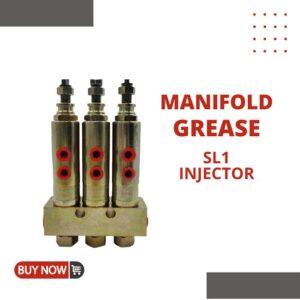
Single and manifold injectors are adjustable up to .003 cubic inches discharge per cycle.Each manifold includes two mounting clips and screws
Technical Data
Model |
P.N. | Number outlets | Work pressure | Viscosity | Discharge | A | L |
N | MPa | mm2/s | mL/CY | mm | mm | ||
BL | 33061 | 1 | 5.6
~6.9 |
32-320 | 0.016
~0.049 |
29 | 41 |
33062 | 2 | 48 | 60 | ||||
33063 | 3 | 67 | 79 | ||||
33064 | 4 | 86 | 98 | ||||
33065 | 5 | 105 |
117 |
Adjustment
Injector output is controlled by the position of the indicator cap. The location of the cap determines the travel of the discharge piston. When the indicator is fully tightened onto the measuring chamber,lubricant output is decreased to a minimum. Retracting the indicator cap two full turns permits a maximum of .003 cu. in. to be discharged. Turning the indicator cap beyond two full turns will not increase lubricant output. When the individual injector has been adjusted to the desired output,tighten locknut against face of the indicator cap.
Check discharge output from injector if cap is adjusted to less than 1/2 turn from minimum.
Use a clean oil type and viscosity as recommended by machine manufacturer. Check compatibility with synthetic lubricants.